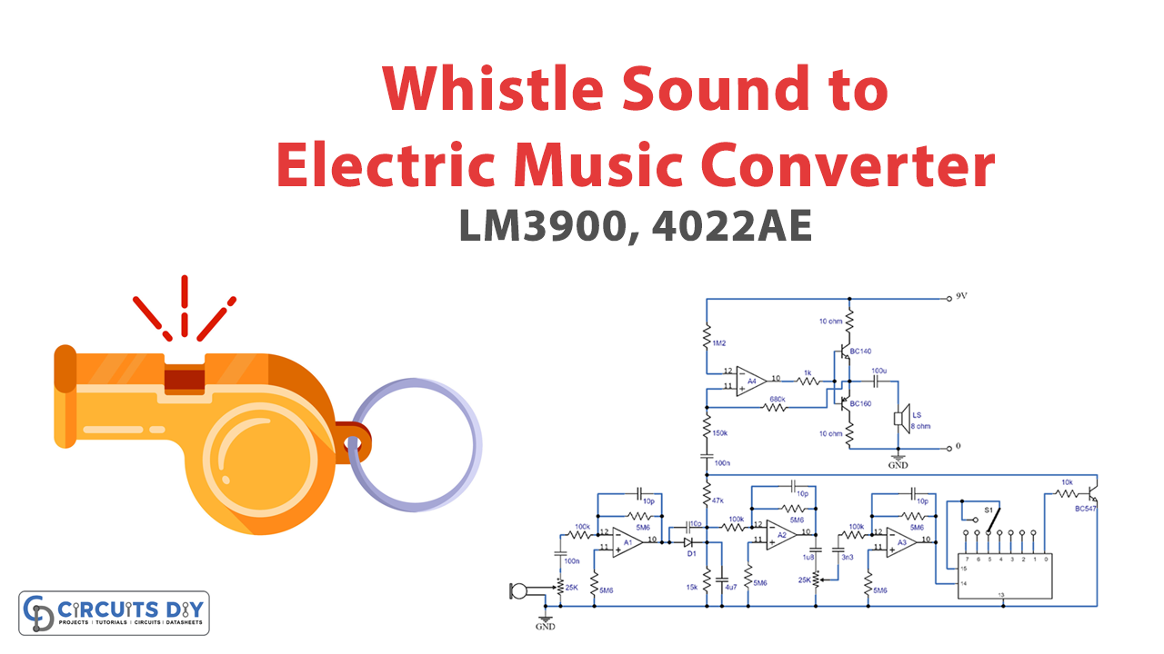
Introduction
Are you struggling to find the time to play an instrument? Do you find yourself whistling tunes in your free time and wish you could turn them into full-fledged musical pieces? Well, you’re in luck! The “Convert Whistle Sound to Electronic Music” circuit is here to turn your whistles into a harmonious melody, with no musical instrument required. In this blog post, we’ll walk you through the circuit’s inner workings and show you how to make your own music with ease.
Hardware Required
You will require the following hardware for converting Whistle Sound to Electronic Music Circuit.
| Components | Value | QTY |
| IC | LM3900, 4022AE | 1, 1 |
| Polar Capacitor | 47u, 100u | 1, 2 |
| Non Polar Capacitor | 100n 10p, 1n5, 1n8, 3n3, 15p | 1, 1, 1, 1, 1, 2 |
| Resistor | 100k, 5M6, 15K, 3M3, 47K, 10K,1M2, 150K, 680K, 1K, 10 | 2, 4, 1, 2, 1, 1, 1, 1, 1, 1, 2 |
| Variable Resistor | 25k | 2 |
| Diode | – | 1 |
| Transistor | bc160, bc140, | 1, 1 |
| Speaker | 8ohm | 1 |
Block Diagram: Simplifying the Process
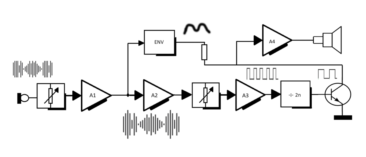
The “Easy Music” principle is easy to understand, as depicted in the block diagram. An op-amp (A1) is used to amplify the musician’s whistle picked by the crystal microphone. A portion of the signal is fed into an envelope follower, where it is rectified and filtered to produce a positive voltage. The positive voltage follows the input signal’s amplitude envelope, resulting in a square wave output with similar amplitude dynamics as the input signal.
Circuit Diagram
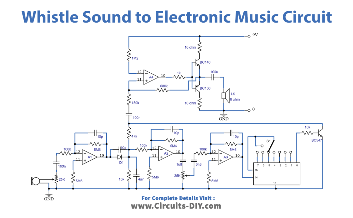
How the Circuit Works
The circuit diagram (shown above) has multiple sections, each serving a unique purpose. P1 acts as a sensitivity control. A1, with a gain value of 56, is used as a linear amplifier. C4 stores the peak voltage produced by rectifying a part of the output signal, which A2 and A3 amplify.
The combined gain of A1 to A3 is sufficient to cause limiting at A3 output. The limiting is done with the smallest input signals adjusted by P2. P2 is responsible for adjusting the gain of the limiting amplifier so that it can be done with the smallest input signals, avoiding noise-induced limitations.
S1 is used for the division of a CMOS counter, whereas A3’s output is used for clocking. IC2 switches transistor T1 on and off. The collector signal’s amplitude varies according to the input signal since C4 supplies voltage to the collector resistor (R6) of T1. Finally, an audio power amplifier built around A4 amplifies the signal, driving a small loudspeaker.
Final Words
In a world that’s always on the go, taking the time to create music can be a challenge. But with this easy circuit, you can effortlessly turn your whistles into electronic music. The circuit’s simple yet powerful design makes it an excellent tool for anyone looking to add a touch of creativity to their daily lives. Try this circuit, and feel free to ask questions in the comment section. Happy building!