Introduction
To secure the various process in different industries, heat is an important physical measurement. As you know that industries have furnaces, freezing substances, and melting machines, therefore in industries and the industrial process, temperature indicators play a vital role. Usually, they are used to determine the temperature readings or levels. Moreover, it prevents the machines and environment from any hazardous or physical harm. Several temperature sensors and indicators are available in the market. We are using a sensor that uses a few components. So, in this tutorial, we are going to “Heat Sensor Circuit”
Hardware Required
| S.no | Component | Value | Qty |
|---|---|---|---|
| 1. | NTC Thermistor | 2.2KΩ | 1 |
| 2. | NPN Transistor | BC547 | 1 |
| 3. | Buzzer | 9V | 1 |
| 4. | Potentiometer | 10K | 1 |
| 5. | Capacitor | 1uF | 1 |
| 6. | Battery | 9V | 1 |
| 7. | 2-Pin Connector | – | 1 |
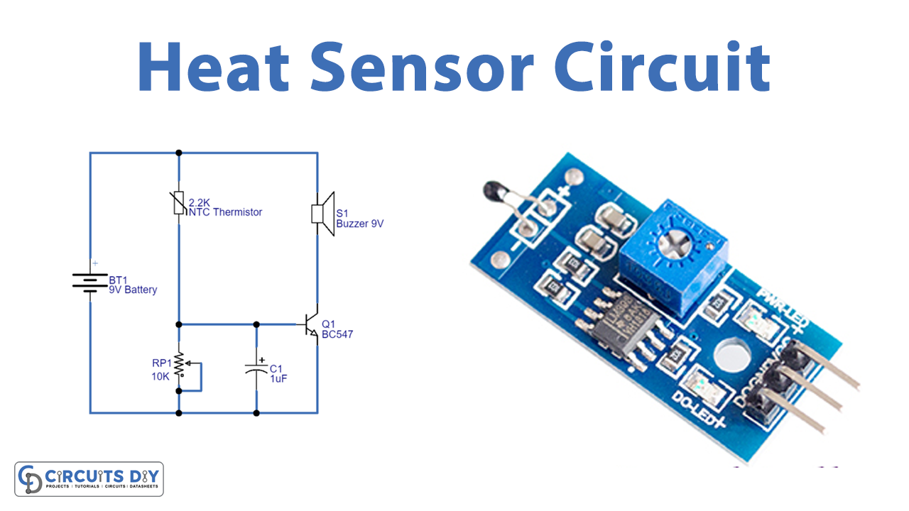
Circuit Diagram
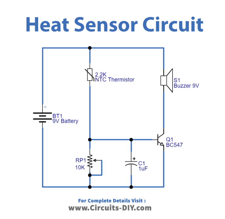
Working Explanation
In this Heat Sensor Circuit, NPN transistor BC547 is working as a switch. Hence buzzer turns ON when the temperature increases over the threshold voltage and turns OFF when the temperature is below the threshold voltage. The NTC thermistor temperature of 2.2K is wired with the Potentiometer and to the base of transistor Q1. Thus the base of Q1 is getting biased through the thermistor potentiometer. The resistance of the potentiometer determines the temperature threshold. When there is no temperature, in this case, the thermistor provides full resistance to the base terminal of the transistor. When the temperature gets increases, the resistance of the thermistor gets decreases. Hence transistor gets turned ON and makes the buzzer noise.
Application and Uses
- It can be used in digital thermometers.
- This circuit can be found in the fire alarm circuit.
- It can be used in refrigerators and ovens.
- Circuit breakers can also utilize this circuit.