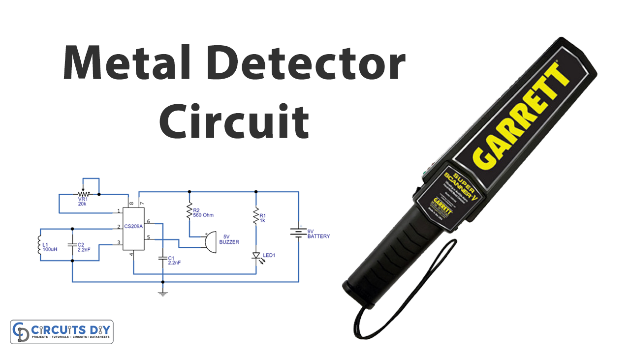
In this tutorial, we are going to make a “Metal Detector Circuit”.
Nowadays security/safety is one of the few things that is a priority regardless of where you are in the world, that’s why security check-in in most public and private places is provided. There are different types of metal detectors like handheld metal detectors, walk-through metal detectors, and ground search metal detectors. In the case of security officers, they either use walk-in metal detectors or wands.
Here we design a simple metal detector circuit by employing IC CS209A from a cherry semiconductor (now it’s on semiconductor), the CS209A is a bipolar monolithic integrated circuit that consumes a 12V single power supply and utilizes 6mA current during operation. It can provide output current sink capability up to 100mA, and IC CS209A comes in 14-pin and 8-pin configurations, and also it is available in DIP 8, and SOP 14 packages. It is widely used in metal detector applications and Inductive proximity sensing applications.
Hardware Required
| S.no | Component | Value | Qty |
|---|---|---|---|
| 1. | IC | CS209A | 1 |
| 2. | Resistor | 560Ω, 1K | 1, 1 |
| 3. | Capacitor | 2.2nF | 2 |
| 4. | Variable Resistor | 20K | 1 |
| 5. | Buzzer | 5V | 1 |
| 6. | LED | – | 1 |
| 7. | Inductor | 100uH | 1 |
| 8. | Connecting Wires | – | – |
| 9. | Battery | 9V | 1 |
Circuit Diagram
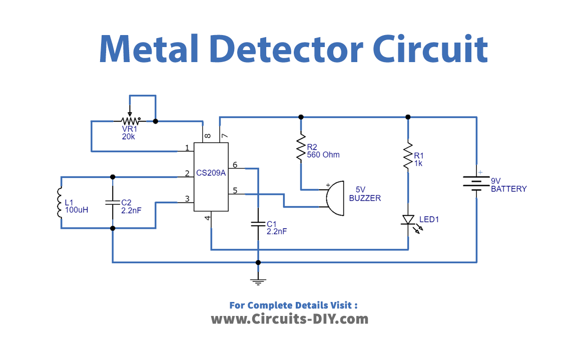
IC CS209A Pin Configuration
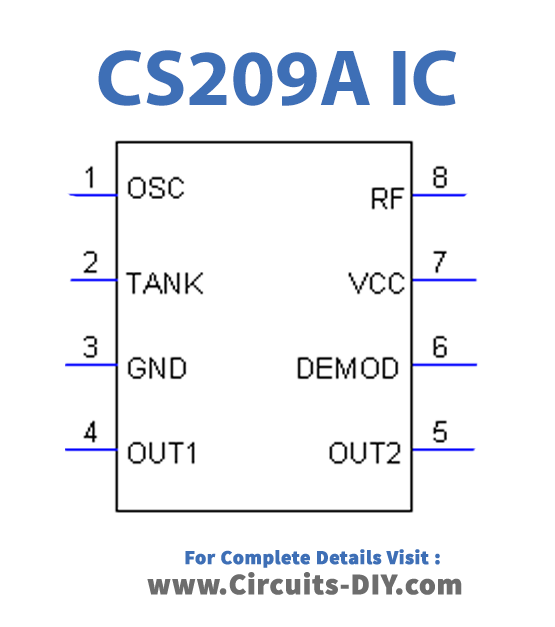
IC CS209A comes in 14-pin and 8-pin configurations, and also it is available in DIP 8, and SOP 14 packages. This IC utilizes a 6mA current and consumes a 12V single power supply during operation. It can provide output current sink capability up to 100mA.
Working Explanation
There are three main parts to the metal detector circuit: the LC Circuit, the proximity sensor, the output LED, and the buzzer. An important part of this circuit is designing the inductor coil L1 because the sensitivity and output result is based on this inductor only. Here L1 value was obtained to 100μH using an insulated copper coil of 0.4mm wire, the L1 has 40mm in diameter and is made of 50 turns. The coil and the capacitor C1, which are connected in parallel, will form the LC circuit. The LC circuit, including the L1 and C1, gets any resonating frequency to a metal close. As a result, the metal and magnet attraction will create an electric field. The result will lead to the induction of current in the coil. Lastly, it will change the signal flow through the receive coil. The IC CS209A has an internal oscillator circuit and L1 acts as a tank element, hence the change of inductance in L1 near metal objects makes output 2 as high. Here OUT 1 is connected with LED and OUT 2 is connected with a 5V buzzer, this buzzer makes a noise when the metal is detected. The sensitivity of this circuit can be varied by using variable resistor VR1(The variable resistor will change the proximity sensor value to equal the LC circuit). For this circuit, the detector coil L1 should be near the metal objects to detect and give a buzzer sound. The R1 and R2 resistors will limit the current flow in LED and buzzer.
Applications
The applications of metal detectors are many. You can see them in airports and anywhere that needs a security check for entry.
Can be used to detect metal objects in conveyor belts. In food processing industries no metals must be accidentally included so having a metal detector near the conveyor belts which carry the items for packing will do the job.