Overview
In the world of IoT (Internet of Things), the ability to gather data from the environment and display it in a user-friendly manner is paramount. One of the key components in such a setup is a sensor capable of measuring temperature, humidity, and barometric pressure simultaneously. The BME280 sensor fits this requirement perfectly, offering high accuracy and a compact form factor.
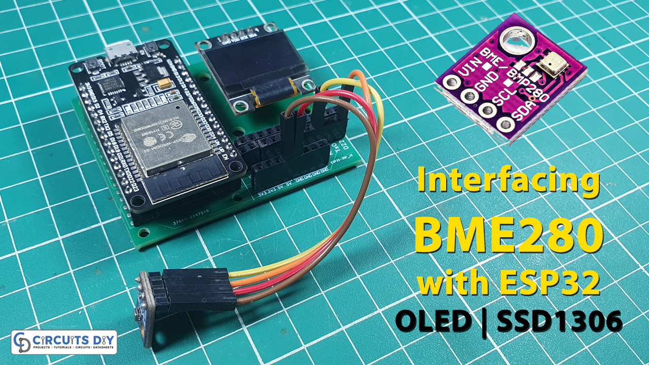
In today’s tutorial, we are going to Interface the “BME280 Temperature, Humidity, and Atmospheric Pressure Sensor Module” with ESP32 Microcontroller & Display its reading on OLED SSD1306.

PCBWay commits to meeting the needs of its customers from different industries in terms of quality, delivery, cost-effectiveness, and any other demanding requests. As one of the most experienced PCB manufacturers in China. They pride themselves to be your best business partners as well as good friends in every aspect of your PCB needs.
What is BME280
The BME280 is a highly integrated environmental sensor developed by Bosch Sensortec. It combines three key environmental sensing capabilities in a single device, making it a popular choice for various applications in the fields of weather monitoring, indoor climate control, IoT devices, and more. The acronym “BME” stands for Barometric Pressure, Humidity, and Temperature, indicating the primary parameters it can measure.
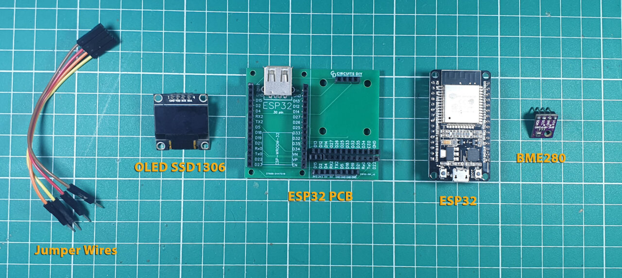
Hardware Components
You’ll need the following hardware components to get started:
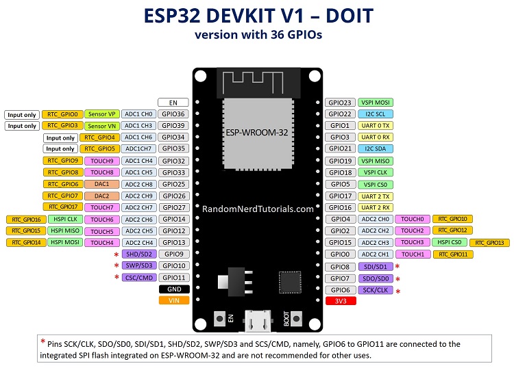
ESP32 Pinout
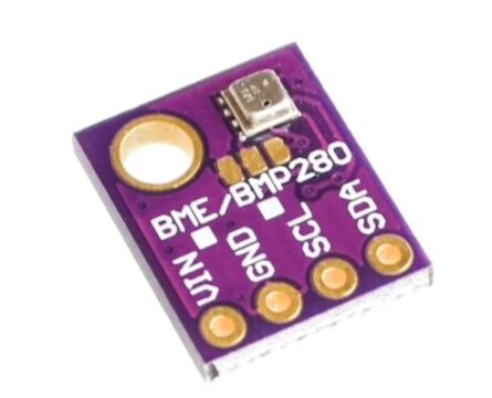
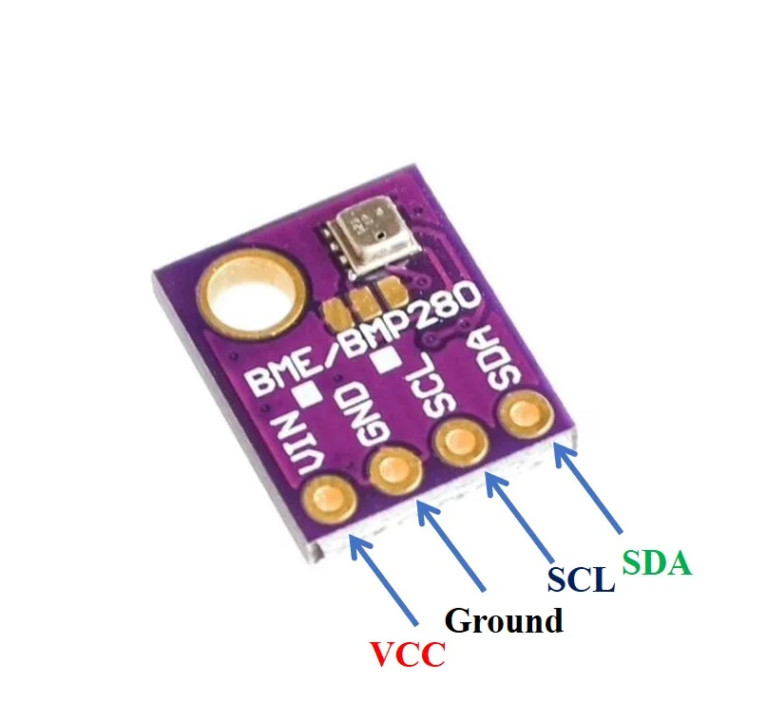
BME280 Pinout
For details datasheet of ABC Sensor Pinout visit this link.
Steps-by-Step Guide
(1) Setting up Arduino IDE
Download Arduino IDE Software from its official site. Here is a step-by-step guide on “How to install Arduino IDE“.
(2) ESP32 in Arduino IDE
There’s an add-on that allows you to program the ESP32 using the Arduino IDE. Here is a step-by-step guide on “How to Install ESP32 on Arduino IDE“.
(3) Include Libraries
Before you start uploading a code, download and unzip the
library at /Program Files(x86)/Arduino/Libraries (default). Here is a step-by-step guide on “How to Add Libraries in Arduino IDE“.
(4) Schematic
Make connections according to the circuit diagram given below.

Wiring / Connections
| ESP32 | OLED Display | BME280 |
|---|---|---|
| 3V3 | VCC | VIN |
| GND | GND | GND |
| GPIO21 | SDA | SDA |
| GPIO22 | SCL | SCL |
(5) Uploading Code
Now copy the following code and upload it to Arduino IDE Software.
#include <Wire.h>
#include <SPI.h>
#include <Adafruit_Sensor.h>
#include <Adafruit_BME280.h>
#include <Adafruit_GFX.h>
#include <Adafruit_SSD1306.h>
/*#include <SPI.h>
#define BME_SCK 18
#define BME_MISO 19
#define BME_MOSI 23
#define BME_CS 5*/

#define SEALEVELPRESSURE_HPA (1013.25)

Adafruit_BME280 bme; // I2C
//Adafruit_BME280 bme(BME_CS); // hardware SPI
//Adafruit_BME280 bme(BME_CS, BME_MOSI, BME_MISO, BME_SCK); // software SPI

Adafruit_SSD1306 display = Adafruit_SSD1306(128, 32, &Wire);
unsigned long delayTime;

void setup() {
  Serial.begin(9600);
  Serial.println(F("BME280 test"));

  // by default, we'll generate the high voltage from the 3.3v line internally! (neat!)
  display.begin(SSD1306_SWITCHCAPVCC, 0x3C);  // initialize with the I2C addr 0x3C (for the 128x64)
   // init done
  display.display();
  delay(100);
  display.clearDisplay();
  display.display();
  display.setTextSize(1.2);
  display.setTextColor(WHITE);

  bool status;
  // default settings
  // (you can also pass in a Wire library object like &Wire2)
  status = bme.begin(0x76);
  if (!status) {
    Serial.println("Could not find a valid BME280 sensor, check wiring!");
    while (1);
  }

  Serial.println("-- Default Test --");
  delayTime = 1000;

  Serial.println();
}


void loop() {

  display.setCursor(0,0);
  display.clearDisplay();

  Serial.print("Temperature = "); Serial.print(bme.readTemperature()); Serial.println(" *C");
  display.print("Temperature: "); display.print(bme.readTemperature()); display.println(" *C");

  Serial.print("Pressure = "); Serial.print(bme.readPressure() / 100.0F); Serial.println(" hPa");
  display.print("Pressure: "); display.print(bme.readPressure() / 100.0F); display.println(" hPa");

  Serial.print("Humidity = "); Serial.print(bme.readHumidity()); Serial.println(" %");
  display.print("Humidity: "); display.print(bme.readHumidity()); display.println(" %");

  Serial.println();
  display.display();
  delay(1000);
}
How code works
This code is for interfacing both the BME280 sensor and an SSD1306 OLED display with an Arduino board. It includes necessary libraries for communication (Wire.h, SPI.h) and for working with the BME280 sensor (Adafruit_Sensor.h, Adafruit_BME280.h). It also includes libraries for the SSD1306 OLED display (Adafruit_GFX.h, Adafruit_SSD1306.h).
The setup function initializes serial communication, sets up the OLED display, and checks for the presence of the BME280 sensor. The loop function continuously reads temperature, pressure, and humidity values from the sensor, displays them on the OLED screen, and prints them to the serial monitor. There’s a delay of 1 second between each reading.
Applications
- Environmental monitoring systems
- Weather stations
- Indoor climate control systems
- IoT projects involving temperature, pressure, and humidity sensing
- Educational purposes for learning sensor interfacing and OLED display integration
Conclusion
- The code demonstrates how to interface the BME280 sensor with an ESP32 microcontroller and display sensor readings on an SSD1306 OLED display.
- It provides a practical example of integrating multiple components for environmental data collection and visualization.
- The application can be extended and customized for various IoT projects and educational purposes, showcasing the versatility and ease of use of these components in creating functional systems.
Related posts:
 How to Use OLED Displays with ESP32 Boards
 ESP8266-ESP01 Local Time Internet Clock with OLED SSD1306
 Light Meter using XIAO RP2040 & OLED SSD1306
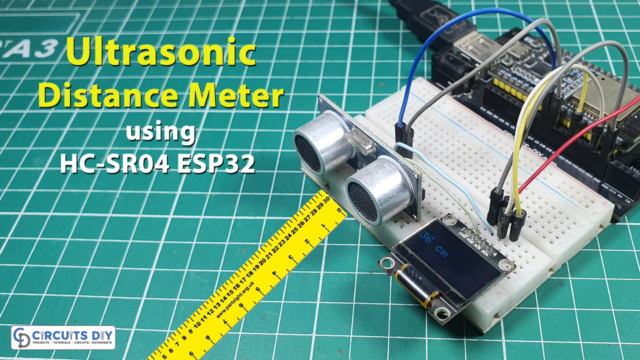 Distance Meter using HCSR04 Ultrasonic Sensor & ESP32
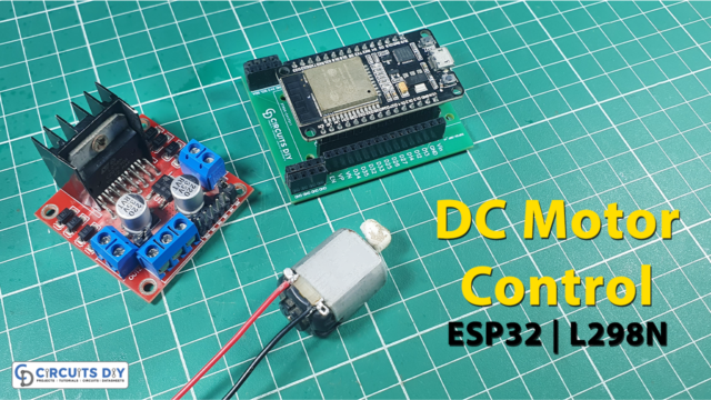 DC Motor Control using L298N Motor Driver & ESP32
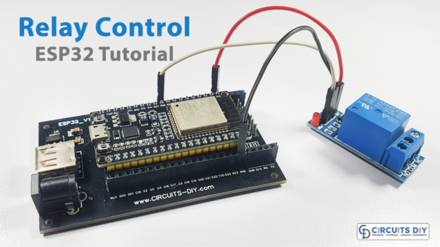 ESP32 Tutorials - Control AC Appliances with Relay (Web Server)


