Overview
In the realm of robotics, automation, and electronic projects, controlling DC motors efficiently and effectively is a fundamental requirement. The combination of an L298N motor driver and an ESP32 microcontroller presents a powerful solution for precise DC motor control in various applications
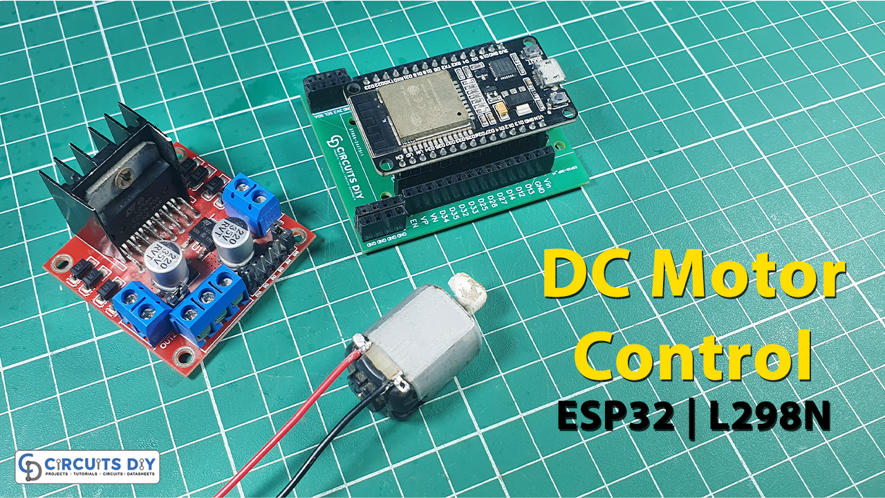
In today’s tutorial, we are going to control “DC Motor” using an L298N Motor Driver & ESP32 Microcontroller.
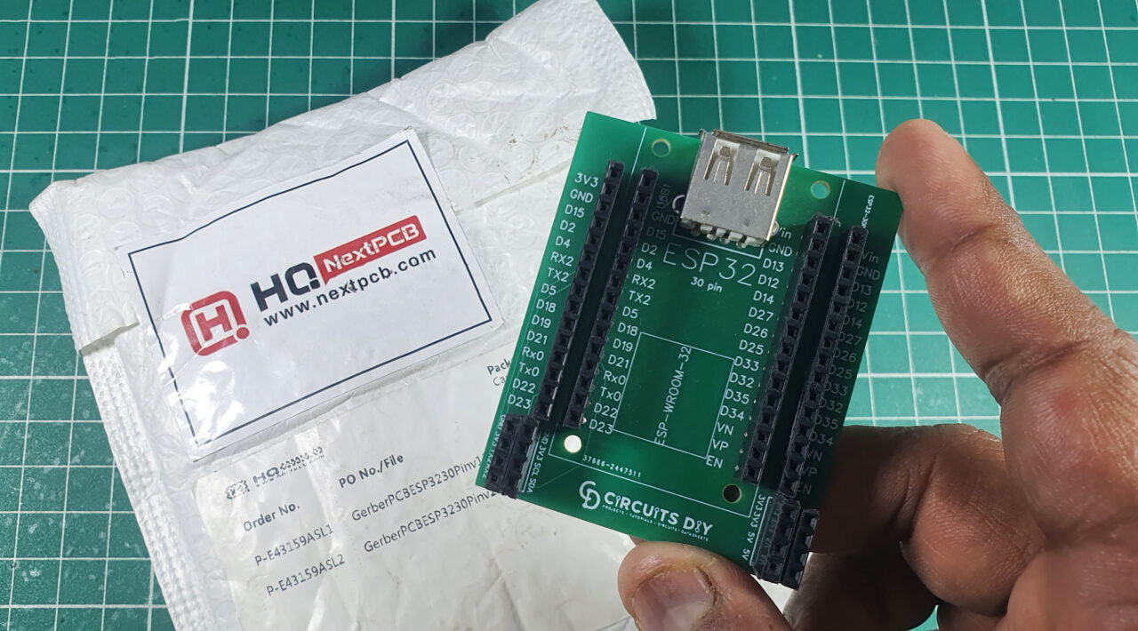
NextPCB is a leading PCB (Printed Circuit Board) manufacturing and assembly company that specializes in providing high-quality PCB solutions to customers worldwide. Experience high-quality and reliable PCB manufacturing with NextPCB, where you can order PCBs starting at just $1.9 and multilayer boards starting at $6.9. NextPCB also offers free PCB assembly for 5 boards, allowing you to bring your designs to life without worrying about assembly costs. Additionally, take advantage of their HQDFM free online PCB Gerber viewer for seamless design verification. NextPCB’s commitment to affordable pricing and advanced tools makes it a top choice for all your PCB needs. Visit their website at NextPCB to explore their services and start your next project today.
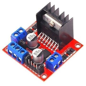
L298N Motor Driver
The L298N motor driver is a dual H-bridge motor driver IC that allows bidirectional control of DC motors. It can drive two DC motors or a single stepper motor and provides a convenient interface for controlling motor speed and direction using a microcontroller.
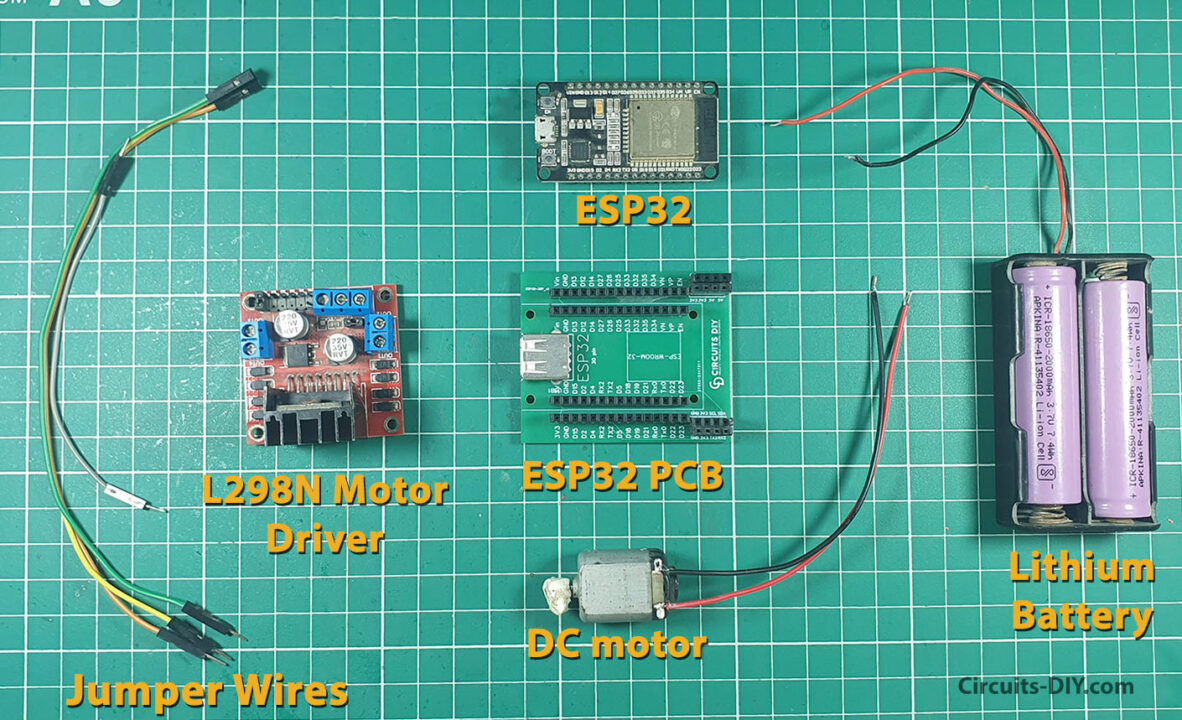
Hardware Components
You’ll need the following hardware components to get started:
| Components | Value / Model | Qty |
|---|---|---|
| ESP32 | DOIT DEVKIT V1 Board | 1 |
| Motor Driver | L298N | 1 |
| Power source | 4x 1.5 AA batteries or Bench power supply | 1 |
| Jumper Wires | – | 1 |
| DC Motor | 9V, 12V | 1 |
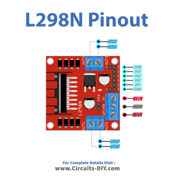
Pinouts
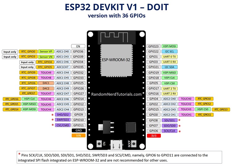
ESP32 Pinout
Steps-by-Step Guide
(1) Setting up Arduino IDE
Download Arduino IDE Software from its official site. Here is a step-by-step guide on “How to install Arduino IDE“.
(2) ESP32 in Arduino IDE
There’s an add-on that allows you to program the ESP32 using the Arduino IDE. Here is a step-by-step guide on “How to Install ESP32 on Arduino IDE“.
(3) Schematic
Make connections according to the circuit diagram given below.
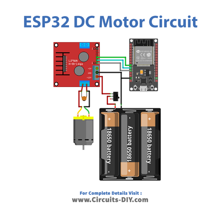
Wiring / Connections
| ESP32 | L298N | External Power |
|---|---|---|
| – | +12v | +12v |
| GND | GND | GND |
| GPIO27 | Input 1 | |
| GPIO26 | Input 2 | |
| GPIO14 | Enable |
(5) Uploading Code
Now copy the following code and upload it to Arduino IDE Software.
// Motor A
int motor1Pin1 = 27;
int motor1Pin2 = 26;
int enable1Pin = 14;

// Setting PWM properties
const int freq = 30000;
const int pwmChannel = 0;
const int resolution = 8;
int dutyCycle = 200;

void setup() {
  // sets the pins as outputs:
  pinMode(motor1Pin1, OUTPUT);
  pinMode(motor1Pin2, OUTPUT);
  pinMode(enable1Pin, OUTPUT);

  // configure LED PWM functionalitites
  ledcSetup(pwmChannel, freq, resolution);

  // attach the channel to the GPIO to be controlled
  ledcAttachPin(enable1Pin, pwmChannel);

  Serial.begin(115200);

  // testing
  Serial.print("Testing DC Motor...");
}

void loop() {
  // Move the DC motor forward at maximum speed
  Serial.println("Moving Forward");
  digitalWrite(motor1Pin1, LOW);
  digitalWrite(motor1Pin2, HIGH);
  delay(2000);

  // Stop the DC motor
  Serial.println("Motor stopped");
  digitalWrite(motor1Pin1, LOW);
  digitalWrite(motor1Pin2, LOW);
  delay(1000);

  // Move DC motor backwards at maximum speed
  Serial.println("Moving Backwards");
  digitalWrite(motor1Pin1, HIGH);
  digitalWrite(motor1Pin2, LOW);
  delay(2000);

  // Stop the DC motor
  Serial.println("Motor stopped");
  digitalWrite(motor1Pin1, LOW);
  digitalWrite(motor1Pin2, LOW);
  delay(1000);

  // Move DC motor forward with increasing speed
  digitalWrite(motor1Pin1, HIGH);
  digitalWrite(motor1Pin2, LOW);
  while (dutyCycle <= 255){
    ledcWrite(pwmChannel, dutyCycle);
    Serial.print("Forward with duty cycle: ");
    Serial.println(dutyCycle);
    dutyCycle = dutyCycle + 5;
    delay(500);
  }
  dutyCycle = 200;
}
How code works
This code sets up and controls a DC motor (Motor A) using an ESP32 microcontroller. It defines the pins for motor control (motor1Pin1, motor1Pin2, enable1Pin) and sets PWM properties for speed control. The setup function initializes the pins and LED PWM functionalities, while the loop function sequentially moves the motor forward at maximum speed, stops it, moves it backward, stops it again, and then gradually increases the speed in the forward direction using PWM. The code also includes serial communication for testing and monitoring the motor’s behavior.
Applications
- Robotics projects requiring precise DC motor control.
- Automated systems such as conveyor belts and robotic arms.
- Home automation projects for controlling window blinds or door locks.
- CNC machines for controlling spindle motors or positioning systems.
- DIY projects like RC cars, drones, or robotic vehicles.
Conclusion
The code snippet demonstrates how to control a DC motor using an ESP32 microcontroller and PWM techniques. With this setup, users can achieve bidirectional motor control, adjust motor speed dynamically, and integrate it into various electronic projects and automation systems with ease.