Introduction
In our different articles, we have discussed DC motor speed controls. So, we thought to discuss the AC motor controller in this article. So, In this tutorial, we are going to make an “Ac power motor speed control circuit” In the AC motor controller, the AC motor receives the power transformed by the controller into adjustable frequency. There are different ways to control AC power. We will try to discuss the controller using SCR.
If you are a beginner and don’t know about SCR, then know that SCR is a three-terminal device and is an abbreviation of a Silicon Control Rectifier. Moreover, it’s a unidirectional switch and has four layers of semiconductors. Thus, SCR can only control either the negative or positive half cycle of input alternating current power.
Hardware Required
| S.no | Component | Value | Qty |
|---|---|---|---|
| 1. | SCR | BRY44 | 1 |
| 2. | Diode | BAV21 | 1 |
| 3. | Variable Resistor | 500R | 1 |
| 4. | Capacitor | 2uF, 220V | 1 |
| 5. | Resistor | 1K, 100R | 1 |
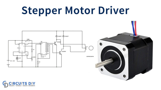
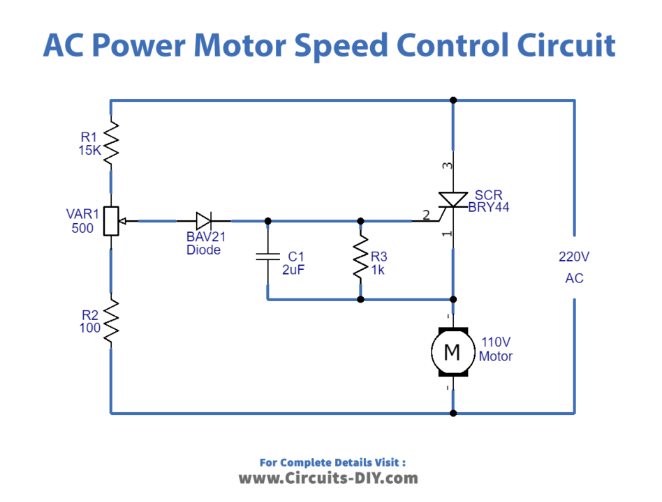
Circuit Diagram
Working Explanation
In this Ac power motor speed control circuit, the motor is controlled by the controlling time of SCR. In other words, you can say that by controlling the on-time or conduction time of an SCR, the voltage across the motor gets varied. Hence the speed may get varied. Further, the conduction time is varied by the firing angle across the diode and the firing angle is varied through the potentiometer. Consequently, the conduction time of the thyristor (SCR) depends upon the value of resistance across the potentiometer, and the motor depends on the conduction time. Thus, one can control the AC power motor easily through this circuit.
Application and Uses
This circuit is particularly to control the AC power motor. So can be used in industrial or in-home automation devices.