A thyristor is a four-layer semiconductor device that conducts current in only one direction. It acts as a bistable switch and only conducts when the gate receives a current trigger. Once the thyristor is triggered, it remains in a conduction state until we reset it manually.
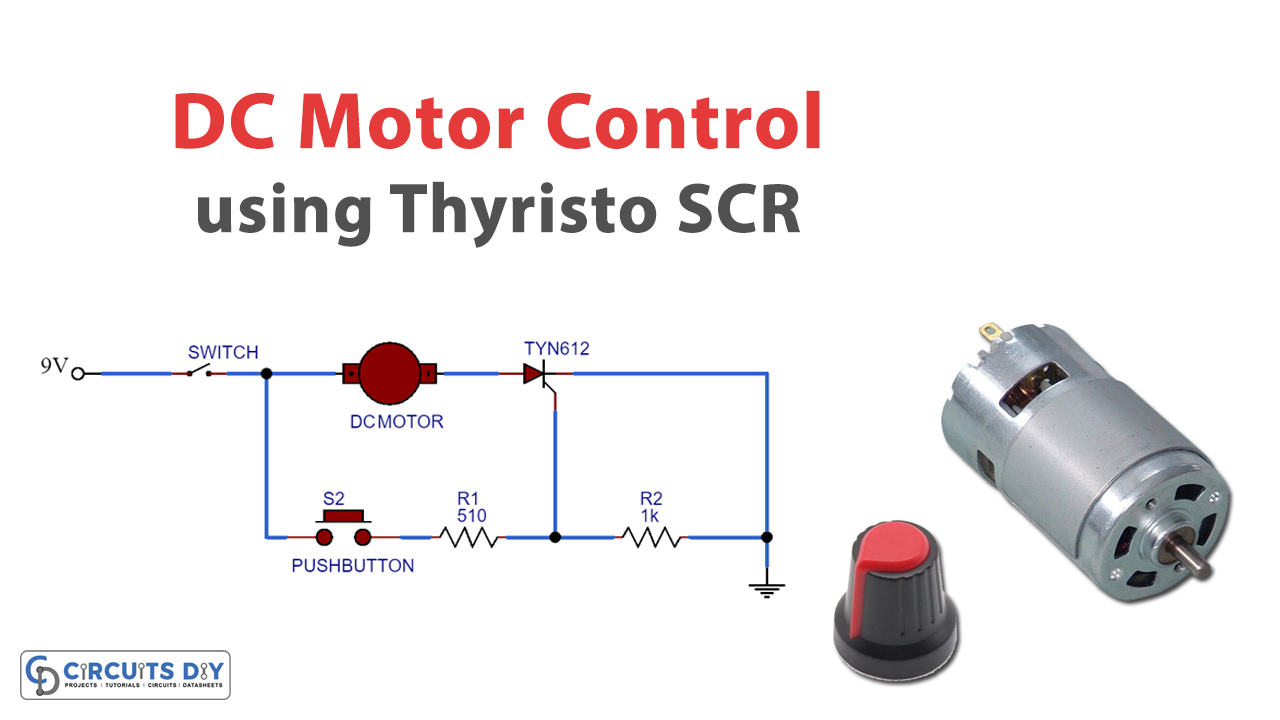
Thyristor switching circuits can be used to control much larger loads such as lamps, motors, heaters, etc. In this tutorial, we will show how to control a DC motor by using a thyristor TYN612. The motor will start when we will apply a pulse to its gate terminal.
Hardware Required
The following components are required to make a DC Motor Control circuit
| S.No | Components | Value | QTY |
|---|---|---|---|
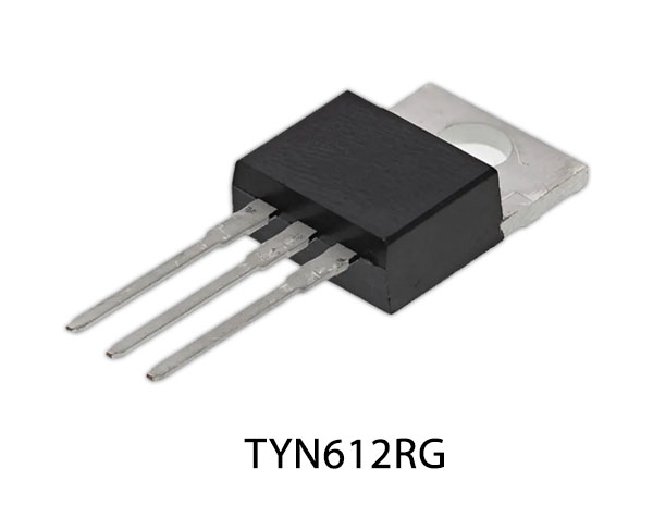
| 1 | Thyristor | TYN612 | 1 |
| 2 | DC motor | – | 1 |
| 3 | Resistor | 510 ohm, 1k | 1 |
| 4 | Switch | – | 1 |
| 5 | Battery | 9V | 1 |
| 6 | Jumper Wires | – | – |
| 7 | Push Button | – | 1 |
TYN612R Pinout
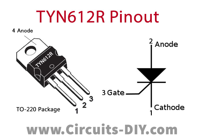
For a detailed description of pinout, dimension features, and specifications download the datasheet of TYN612R
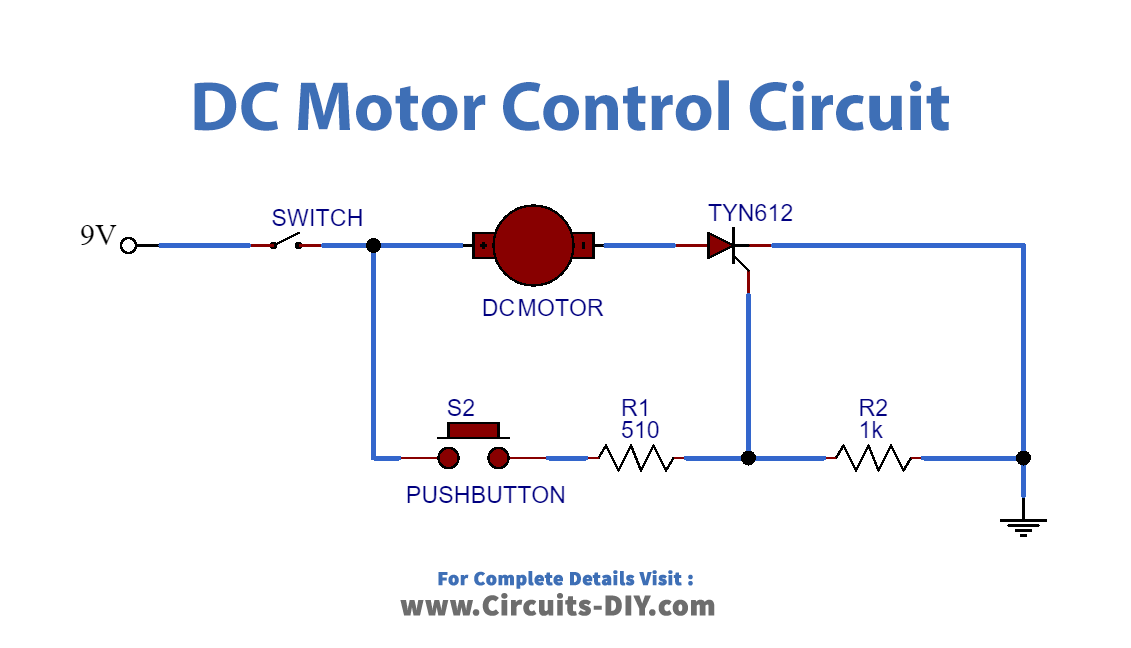
DC Motor Control Circuit
Connections
- Place the Thyristor on the breadboard and connect the cathode terminal to GND.
- Connect one terminal of the DC motor to the Anode terminal of the thyristor and the other terminal to the switch.
- Connect the gate terminal of the thyristor to the resistor and push the button, as shown in the circuit diagram.
- To test the circuit, connect the battery and close the switch S1. When you want to start the motor press the push button and to turn off the motor, open the switch S1.
Working Explanation
In this circuit, the switch S1 is used to RESET or turn OFF the circuit. When the switch S1 is closed, the motor will not start till the push button is not pressed. The push button is used to trigger the thyristor by providing a pulse at the gate terminal of the thyristor. Once a pulse is applied to the gate, the thyristor will start conducting and the motor will turn ON.
When the Thyristor is in an ON state, the only way to stop the Thyristor from conducting is to disconnect it from the power supply. For this, we will use switch S1 which cuts the power supply of the circuit and the Thyristor gets RESET or turns OFF. The Resistor R1 is used to provide sufficient gate current to turn ON the thyristor. While Resistor R2 will prevent the thyristor from false triggering by decreasing the sensitivity of the gate.
Applications
- Thyristor circuits can be used in light dimmers.
- Thyristors can also be used to control the speed of the motors.