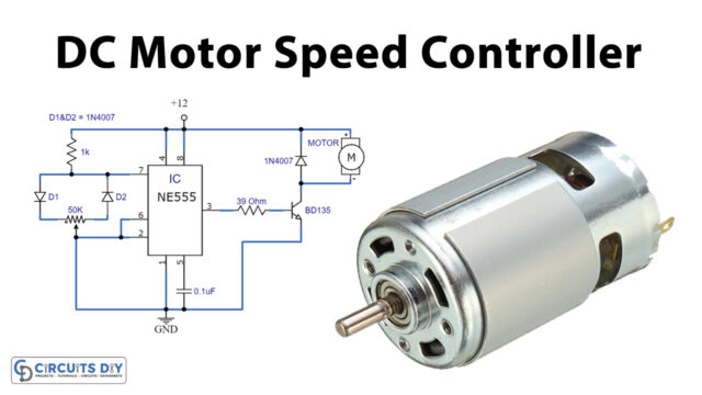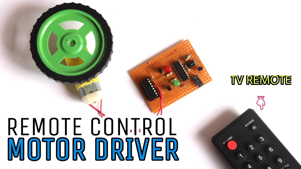
AC/DC motors are an integral part of today’s electrical/mechanical industry & also play an important role in all its other subdivisions. AC & DC Motors have an influence on almost every aspect of today’s electronics whether it be consumer electronics, such as electric toothbrushes & blenders, or industrial electronics such as CNC machines that are incorporated in the process control industry. With the new breakthroughs in RF technology & the increasing need for technology size reduction and usage easement, it has become necessary to introduce an alternative method to properly drive these AC/DC motor drives with reduced physical engagement. So, in this project, we take a look into a step-by-step process on ‘How To Make An RC Motor Driver Circuit Using CD4017 IC & an IR sensor.
JLCPCB is the foremost PCB prototype & manufacturing company in china, providing us with the best service we have ever experienced regarding (Quality, Price Service & Time).
Hardware Components
The following components are required to make Remote Control RC Motor Driver Circuit
| S.no | Component | Value | Qty |
|---|---|---|---|
| 1. | DC Motor | 5V – 9V | 1 |
| 2. | Decade Counter IC | CD4017 | 1 |
| 3. | Comparator IC | LM293/LM393 | 1 |
| 4. | IR receiver | TSOP1738 | 1 |
| 5. | IR Transmitter | – | 1 |
| 6. | NPN Transistors | BC547 | 2 |
| 7. | PNP Transistors | BC557 | 1 |
| 8. | LED | 5mm | 2 |
| 9. | Capacitor | 47uF, 100nF | 2 |
| 10. | Resistor | 150K, 1K, 470 Ohm, 10 Ohm | 6 |
| 11. | Soldering Iron | 45W – 65W | 1 |
| 12. | Soldering Wire with Flux | – | 1 |
| 13. | Veroboard | – | 1 |
| 14. | Jumper Wires | – | As per need |
| 15. | DC Battery with Clip | 4V | 1 |
CD4017 Pinout
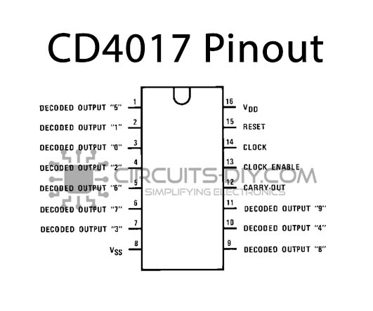
For a detailed description of pinout, dimension features, and specifications download the datasheet of CD4017
LM393 Pinout
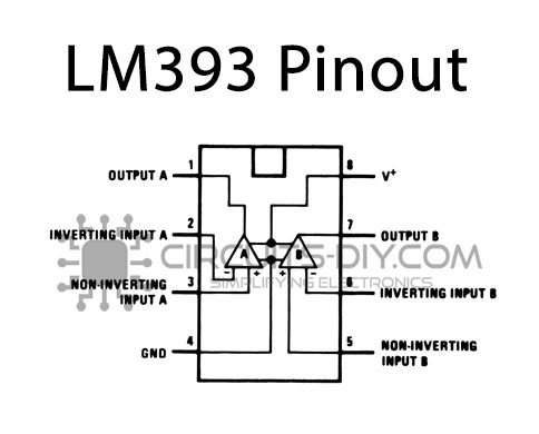
For a detailed description of pinout, dimension features, and specifications download the datasheet of LM393
Useful Steps
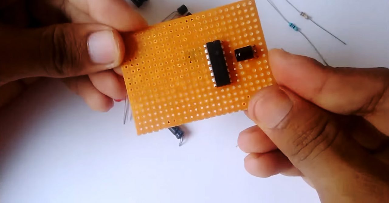
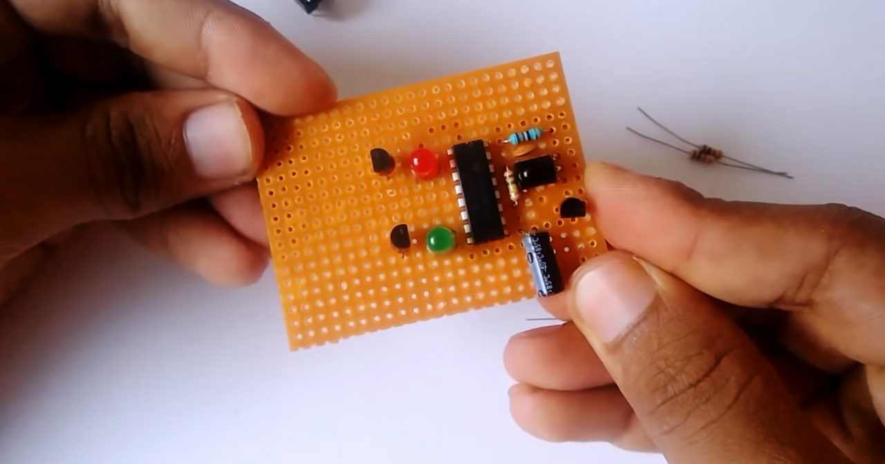
1) Solder the CD4017 IC on the Veroboard, after that solder the middle terminal of the IR receiver to pin 13 of the IC.
2) Solder a 16 Ohm resistor between pin 16 & Vcc of the IR receiver. After that, solder a 47uF capacitor between pin 13 of the IC & the output (signal) pin of the receiver.
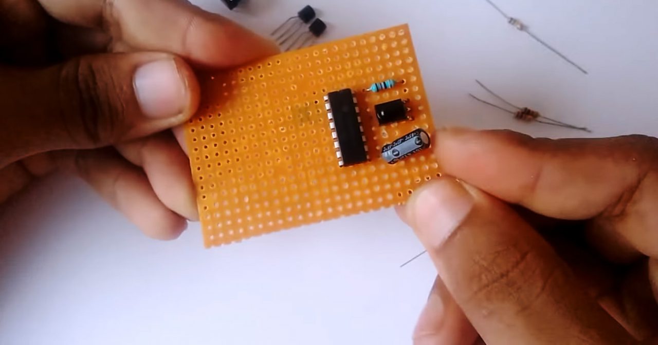
3) Solder the collector of the BC557 transistor to pin 14 IC, base to the output pin of the IR receiver & emitter to pin 16 of the IC.

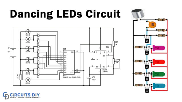
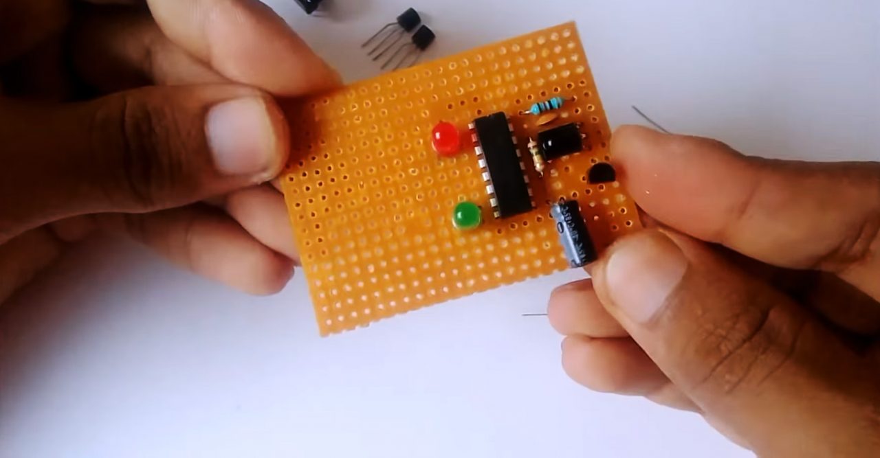
4) Solder a 150K resistor & a 100pF capacitor between pin 13 & pin 14 of the IC. Then, solder the +ve terminal of the green LED to pin 7 & -ve terminal to pin 13 of the IC. Also, solder the +ve terminal of the red LED to pin 2 & -ve terminal to pin 13 of the IC.
5) Solder the emitter of the two BC547 transistors to pin 13 of the IC.
6) Solder two 470 Ohm resistors to the base of each BC547 transistors & pin 2 of the counter IC.

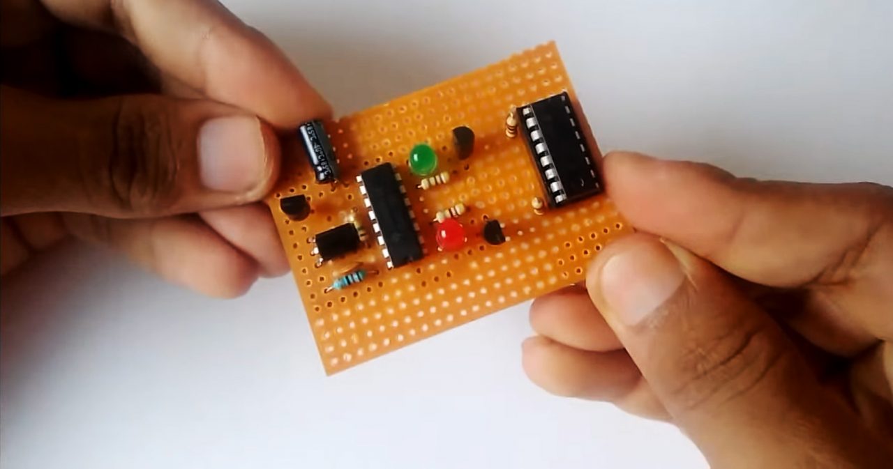
7) Solder the LM293/393 Comparator IC on the Veroboard.
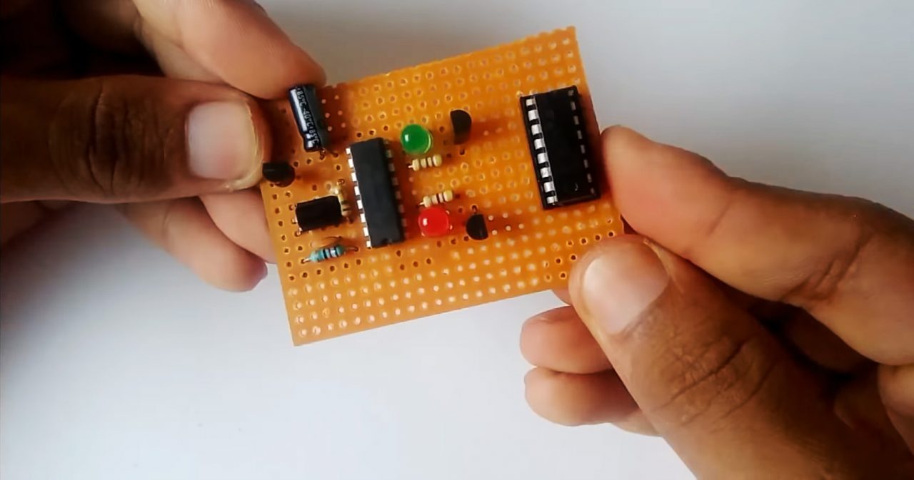
8) Solder a 1K resistor to Pin 16, 1, 8, 9 & 2 of the comparator IC. After that solder another 1K resistor to Pin 16, 1, 8, 9 & 7 of the comparator IC. Also, solder the collector terminal of both (Q3 & Q2) BC547 IC to pin 2 & pin 7 of the comparator IC respectively.
9) Connect the +ve terminal of the 4V Battery to pin 16 & the -ve terminal to pin 8 of the CD4017 IC & LM293 Comparator.

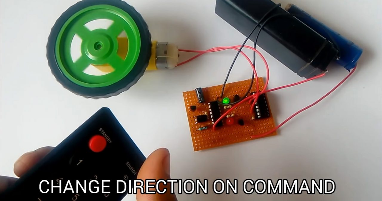
10) Power up & test the circuit.

Working Explanation
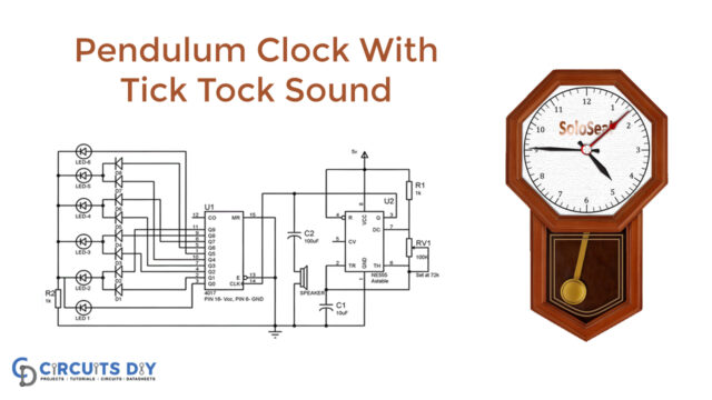
The working of this circuit is as follows, the GND pin of the IR receiver serves as an active low input to trigger the CLK Enable pin of the CD4017 IC. the output signal from the IR sensor goes to the base of the BC557 (Q1). The output is set to trigger from pin 2 for +ve edge & pin 7 in case of the -ve edge of the clock pulse.
The output from the counter IC serves as a control signal for the BC547. The collector output, in turn, is fed to the input of the LM293 comparator, and the comparator output drives the motor in the desired direction.
Applications
- Generally used for driving AC/AC motors for process control applications.