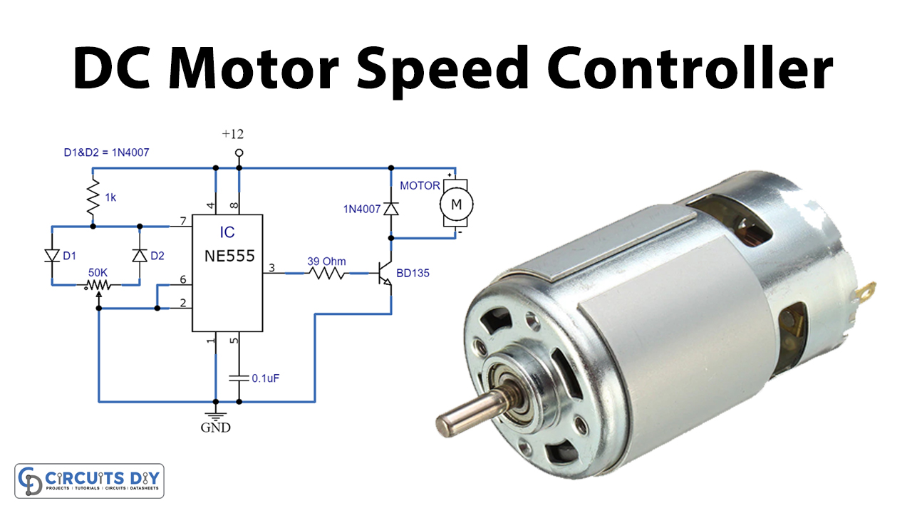
Today we are going to show you how to do DC motor control PWM with 555 timer IC. This is used to control the speed of a DC motor. The main component of this circuit is a NE555 timer IC. This IC is widely used in different circuits and projects since it is versatile, easily available, and inexpensive. It is used to provide oscillations and short or long time intervals in the circuit.
This circuit is easily built in a very short time as it is using only a few components like diodes, resistors, transistors, capacitors, and an IC.

Hardware Components
The following components are required to make DC Motor Control Circuit
| S.no | Component | Value | Quantity |
|---|---|---|---|
| 1. | Input Supply DC | 12V | 1 |
| 2. | Diode | 1N4007 | 3 |
| 3. | Potentiometer | 50K | 1 |
| 4. | Resistor | 1K, 39Ω | 1, 1 |
| 5. | Ceramic Capacitor | 0.1µF | 1 |
| 6. | Motor | – | 1 |
| 7. | IC | NE555 Timer | 1 |
| 8. | Transistor | BD135 | 1 |
NE555 IC Pinout

For a detailed description of pinout, dimension features, and specifications download the datasheet of 555 Timer
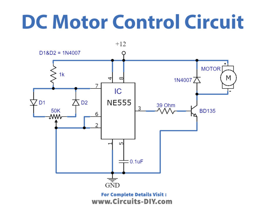
DC Motor Control Circuit
Working Explanation
This circuit is operated at 12 volts DC. NE555 timer IC is working as an astable multivibrator here. A 50K potentiometer along with two diodes is connected to pin 7 (discharge pin) of the 555 IC. By adjusting the potentiometer you can control the speed of the motor. The maximum output current of this IC is 200mA therefore to drive a higher current load of up to 1A we have used a transistor BD135.
For driving a much higher current than 1A you can use other high current transistors like TIP31, 2N3055, etc. using a suitable heatsink because the transistor can become hot during the operation of the circuit.
Applications and Uses
This circuit can be used to control the speed of a DC motor which is used in different things such as conveyors, turntables, etc.