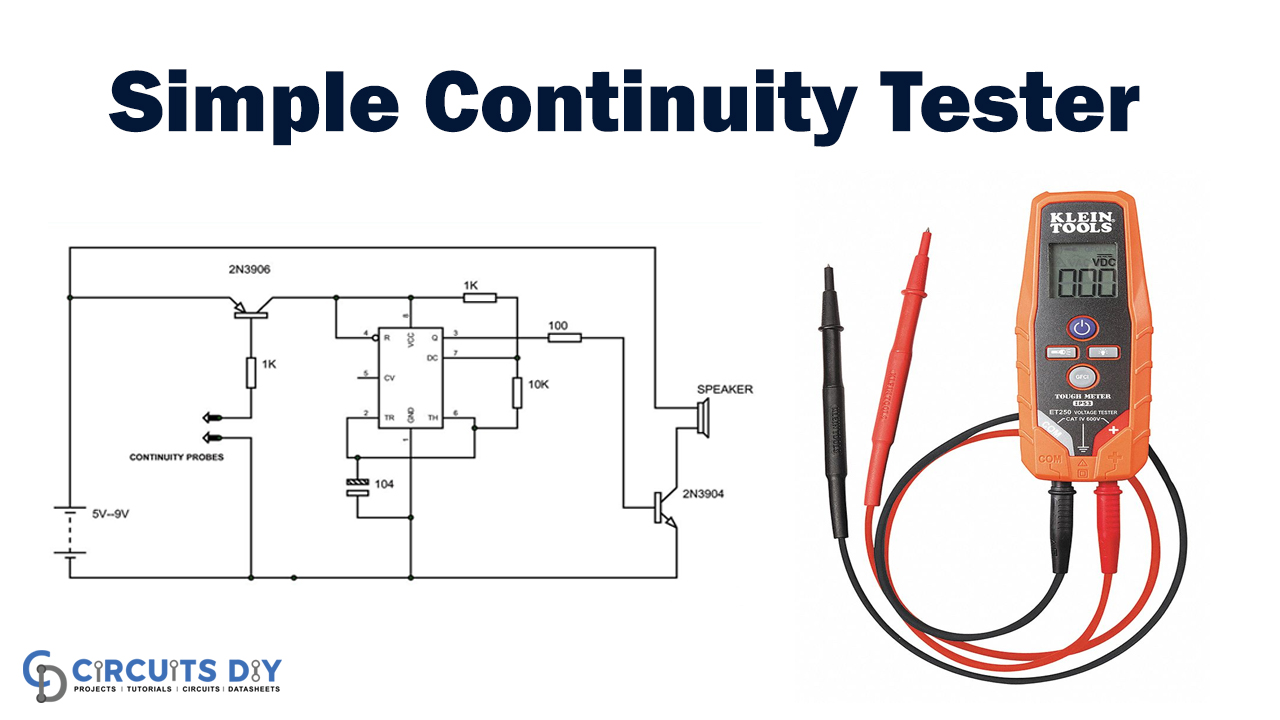
Faults are very common in electronics and electrical systems. The biggest fault occurring is that the connection has ended because the circuit has opened. To remedy such errors, the fault itself can be established across all the lines. This approach is usually replaced. However, with fault scan equipment for continuous checking. There are many ways to measure or classify defects. Continuity Testing is carried out for several circuits and prototypes.
Hardware Component
The following components are required to make the Continuity Tester Circuit
| S.no | Component | Value | Qty |
|---|---|---|---|
| 1. | Supply voltage | +5 to +9 V | 1 |
| 2. | IC | NE555 timer | 1 |
| 3. | Resistor | 100 Ω, 1KΩ, 10KΩ | 1,2,1 |
| 4. | Electrolyte Capacitor | 100nF | 1 |
| 5. | Speaker | 8Ω | 1 |
| 6. | Transistor | 2N3904, 2N3906 | 1 |
| 7. | Testing probes | – | 1 |
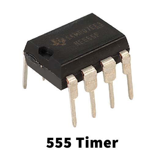
NE555 IC Pinout

For a detailed description of pinout, dimension features, and specifications download the datasheet of 555 Timer
Continuity Tester Circuit
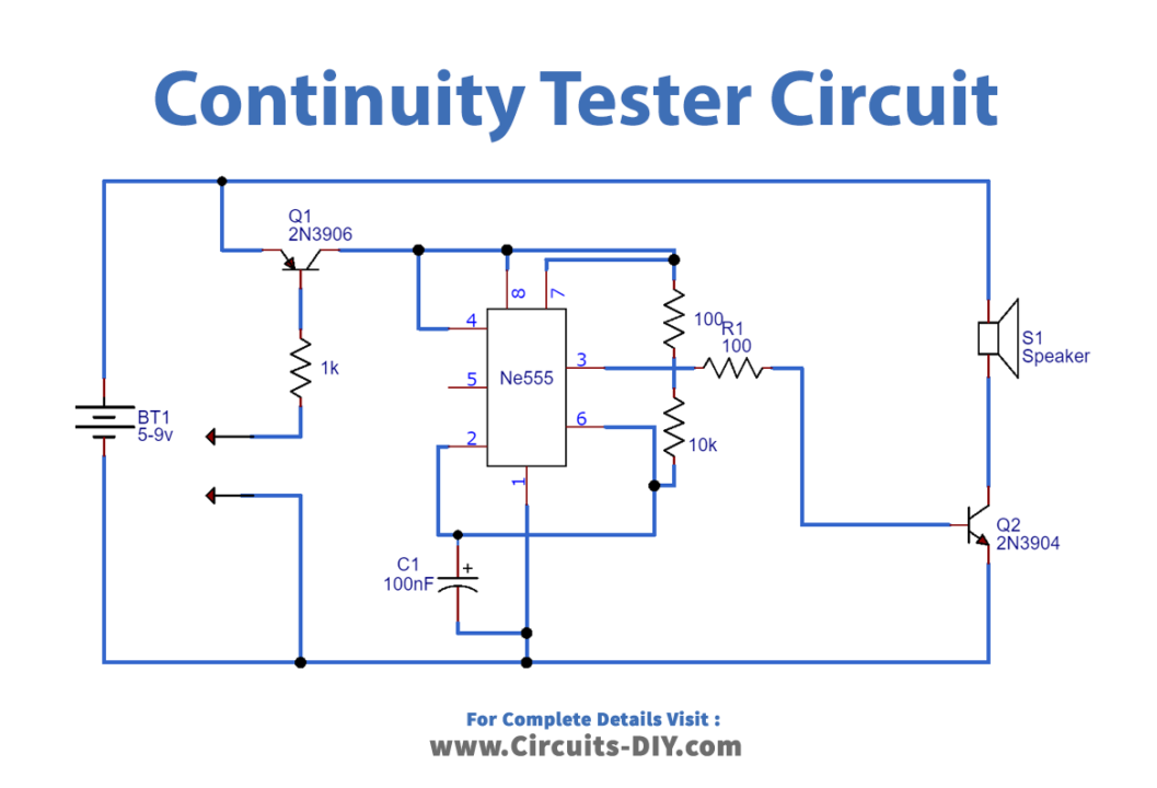
Working Explanation
As shown in the continuity test circuit diagram above, the circuit components are connected. The power is activated. The speaker won’t sound when you turn it on. The power pushed through the PNP transistor is flowing to the timer. As the transistor base is open-circuited, it does not flow through the timer chip, as shown in this diagram. There is, therefore, no square wave at the base of the NPN transistor, and therefore there is no pulse. So no sound is going to be there.
One must keep in mind that the base must be attached to the ground to activate the PNP transistor.
The ground connection at the base, from PNP base to ground, is set to transistor ON when the base of a PNP and the ground is attached to the closed-circuit lines.
The current is passing through the transistor to the timer chip by the transistor ON. With this control, the timer generates sound pulses. When the pair is connected with an open circuit line, the PNP will be off, and there is no power to a timer. No sound implies that this is an open circuit line.
Applications and Uses
A continuity tester is an electrical testing system used to decide if an electrical path between 2 points can be formed, i.e., whether the electrical connexion is made. The test circuit is de-energized until the system is connected.