In this tutorial, we will show you how to make an LED flasher or LED blinking circuit using the 555 Timer IC. This IC creates pulses of current at a specific time interval, and we will use these pulses to create an LED flasher circuit, The time interval of the pulses can be controlled by changing the value of resistors and capacitors used in the circuit

Hardware Components
The following components are required to make LED Flasher Circuit
| S. NO | Component | Value | Qty |
|---|---|---|---|
| 1. | Breadboard | – | 1 |
| 2. | Battery | 9v | 1 |
| 3. | Connecting Wires | – | 1 |
| 4. | IC | NE555 Timer | 1 |
| 5. | Resistors | 1K, 470K | 2, 1 |
| 6. | Capacitor | 1uF | 1 |
| 7. | LED | 5mm | 1 |
555 IC Pinout

For a detailed description of pinout, dimension features, and specifications download the datasheet of 555 Timer
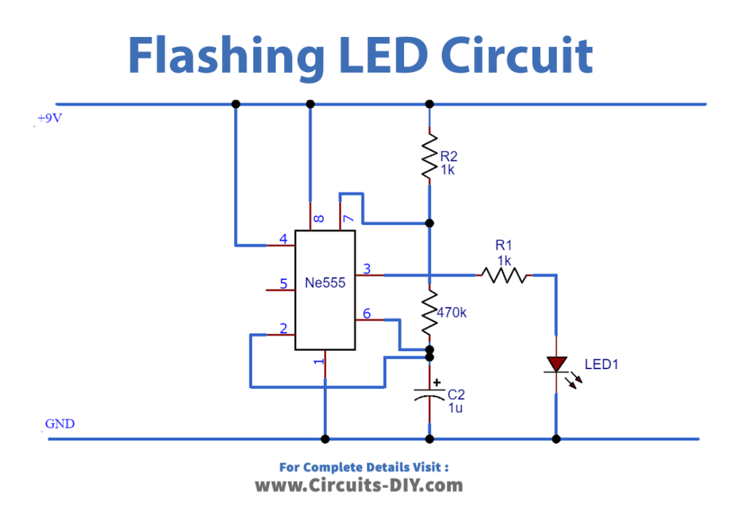
Circuit Diagram
Connection
- Connect PIN 8 of 555 Timer to VCC of battery.
- Connect PIN 1 of 555 Timer to GND of battery.
- Use a jumper wire to connect PIN 6 and PIN 2 of IC.
- Use a jumper wire to connect PIN 4 and PIN 8 of IC.
- Connect 1K resistor between VCC and PIN 7 of IC.
- Connect 1uF capacitor between PIN 2 and PIN 6 of IC
- Finally, connect the LED and 1K resistor at PIN 3 of the 555 timer
Working Explanation
This circuit uses the 555 timers in an Astable mode which generates a continuous output in the form of a square wave via Pin 3. The rate at which LED flashes depends upon the value of the resistor and capacitor used in the circuit. To increase the duty cycle, we will have to use a resistor and capacitors of higher values. If you want to add more LEDs to this circuit, connect each LED in parallel with the first LED using proper resistors.
Application
- This circuit can be used on roads for signaling purposes
- We can create a dancing LED circuit by combining many similar circuits, which we can use for advertisement boards