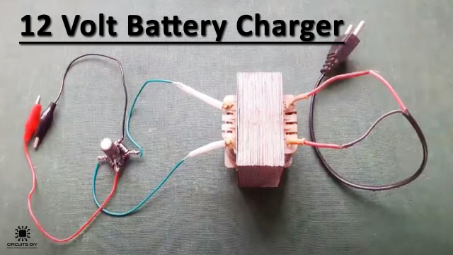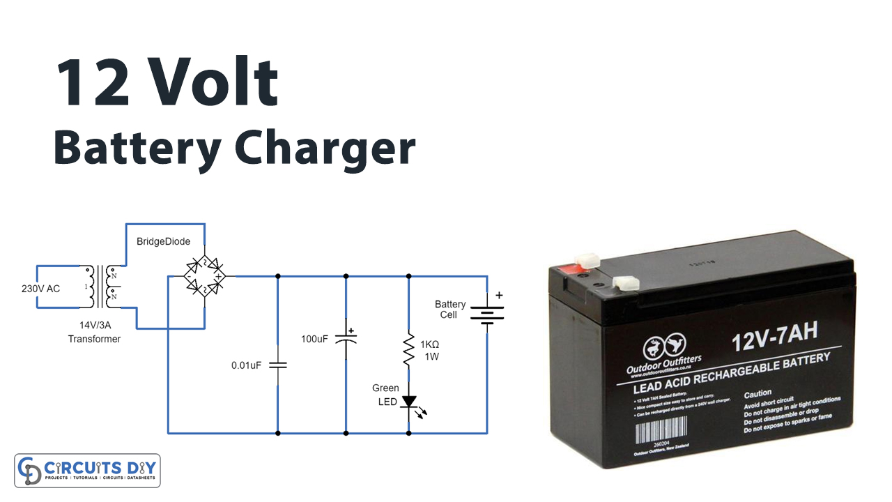
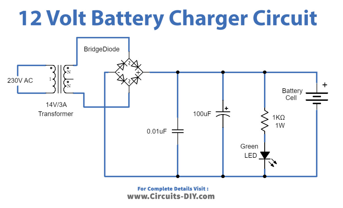
In this tutorial, we are going to make a “Simple 12 Volt Battery Charger Circuit Diagram”.
To charge batteries, we need to put a voltage across the terminals, and the battery starts charging. The charging protocol depends on the size and type of the battery being charged. Some battery types have a high tolerance for overcharging and can be recharged by connection to a constant voltage source or a constant current source, depending on the battery type. If safe charging, fast charging, and/or maximum battery life are important, that’s when things get complicated. Here we design a simple 12-volt battery charger circuit diagram by using a few easily available components, and this circuit is suitable for different types of batteries that need 12 Volt.
This simple 12-volt Battery Charger Circuit diagram gives you an outline design for the general battery charger and you can add additional features to this circuit like reverse polarity protection by placing a diode at the output. (Diode anode to output positive supply and diode cathode as output positive terminal) and over the current protection setup using transistors. The following charger circuit is just a raw prototype to give 12 Volt output to the battery. This circuit is designed to provide a charging current of up to 3 amps.
Hardware Component
The following components are required to make Battery Charger Circuit
| S.no | Component | Value | Qty |
|---|---|---|---|
| 1. | Step down transformer | 0-14V AC / 3 Amps) | 1 |
| 2. | Bridge Rectifier module | BR1010 | 1 |
| 3. | Electrolytic Capacitor | 100µF/25V | 1,1 |
| 4. | Resistor | 1KΩ/1W | 1 |
| 5. | LED | – | 1 |
| 6. | Ceramic Capacitor | 0.01µF | 1 |
Battery Charger Circuit
Working Explanation
As we can see in the circuit at first, we have a power supply section consisting of a 0–14-volt AC step-down transformer, this transformer is used to convert a 230V AC supply into a 12V AC supply, and for AC to DC rectification we have used bridge rectifier module BR1010 which gives highly efficient DC supply with the high current rating. This Bridge Rectifier module will have four terminals, two for AC supply input noted with sign wave and two terminals for DC output noted with a positive and negative sign. The smoothing capacitors C1 and C1. These C1 and C2 capacitors are acting as a filter in this circuit the LED indicates the presence of a DC power supply at the output. Connect the target Battery at the output to get charged. This is the circuit of a simple 12-volt battery charger for a lead-acid battery. It gives 12 volts and 5 Amps current for quick charging of the battery.
Applications
You can use this circuit to charge a 12V SLA battery or 12V Gel cell battery and so on.