All the equipment used in electronics is prone to faults and defects. And much of this equipment contains a bunch of wires, finding faults in them could be a little difficult. We can make a simple and inexpensive circuit to test these wires with a Continuity Tester circuit. A continuity tester circuit is a device that is used to detect the presence of continuity or break between the two ends of a conductor. It consists of two test probes and an LED or a buzzer indicator.
It works when two probes are touched to the two ends of a wire bundle. The indication of continuity in the wire is shown by the activation of an LED or a buzzer. If there is no indication it means that there is some interruption in between the wires.
Hardware Components
| S.no | Component | Value | Qty |
|---|---|---|---|
| 1. | Battery | 9V | 1 |
| 2. | Resistor | 390Ω | 1 |
| 3. | LED | – | 1 |
| 4. | Test probes | – | 2 |
| 5. | Breadboard | – | 1 |
| 6. | Connecting Wires | – | as required |
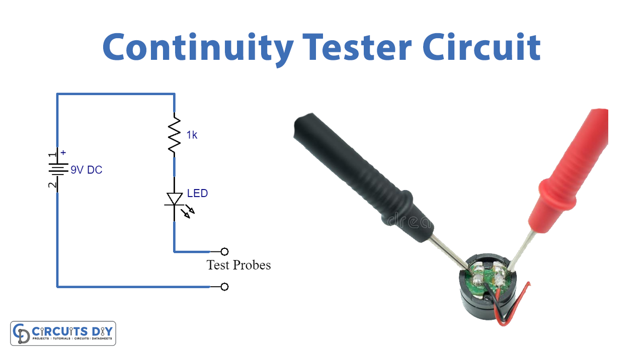
Circuit Diagram

Working Explanation
This is the most simple circuit that is using just a resistor and an LED along with a voltage source. The two testing probes are used to be connected across the two ends of the conductor/wire which needs to be tested. LED is made to switch on through receiving the voltage via the wire/conductor being tested.
If the conductor isn’t broken or the wire has on interruption, then the voltage circulates through it to the LED to complete the circuit which will let the LED glow up. Indicating the equipment is working fine. If the LED does not lights up it shows that your wire or conductor is broken and there is some fault in the equipment.
Applications and Uses
It can be used for.
- Equipment
- PCB tracks
- Wires
- Connections, etc.