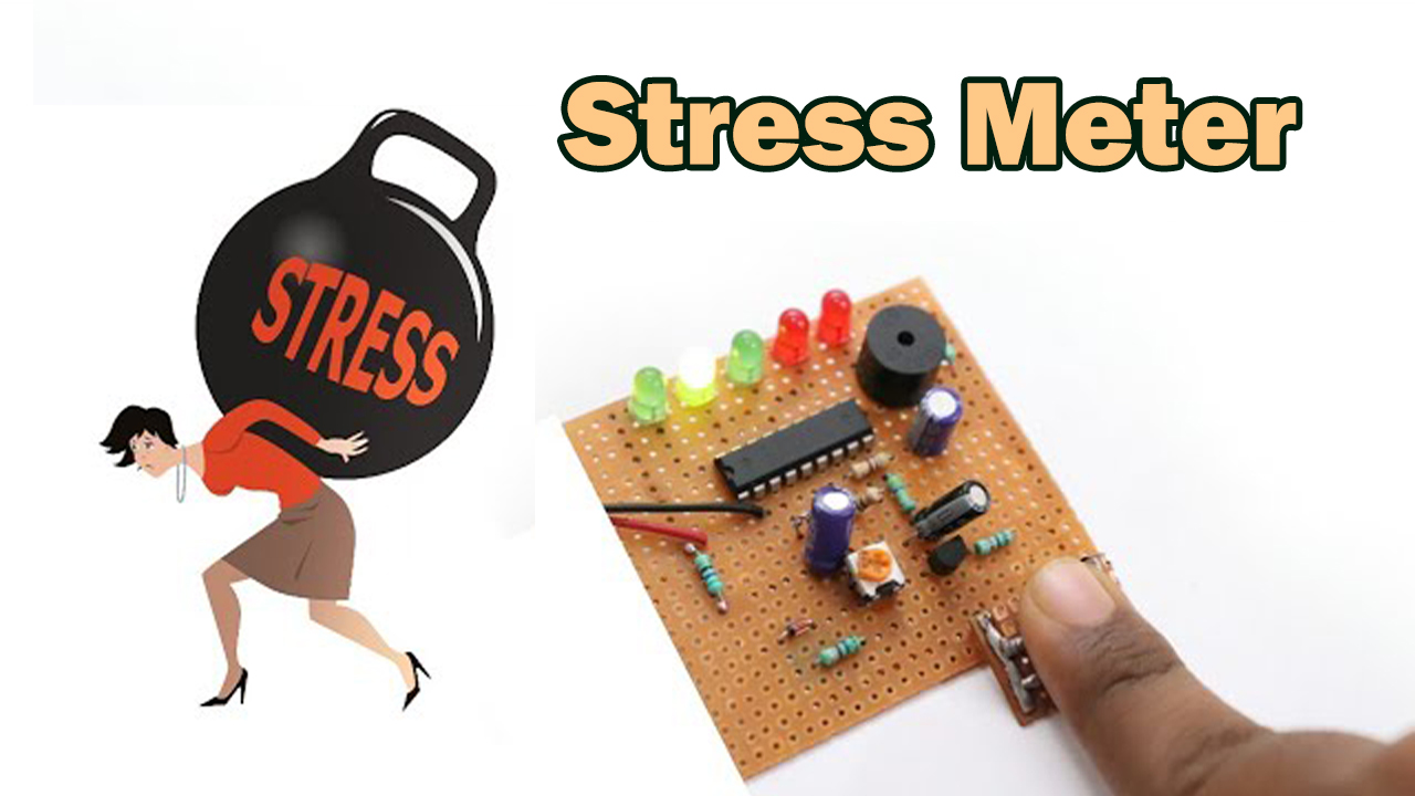
Introduction
The world is working fast. And, since it’s difficult to handle the pace, every other person is getting stressed. The stress of their dreams, the stress to get the dream job, the stress of education, the stress of career, political stress, work stress, family stress, or whatnot. But, engineers have made the electronic device named the stress meter. A stress meter is an electronic device that measures the stress of the body depending on the current flow through the body. The level of human body resistance varies with the stress on our mind and body. The blood flow increases in the stressed body which allows more current to flow across our body.
On the other hand, there is less blood flow in a stress-free and has very resistance, thus resulting in fewer ion concentrations in the. Stress meters generally use ohm’s law in determining the stress by glowing different LEDs.
JLCPCB is the foremost PCB prototype & manufacturing company in china, providing us with the best service we have ever experienced regarding (Quality, Price Service & Time).
Hardware Components
The following components are required to make a Stress Meter Circuit
| S.no | Component | Value | Qty |
|---|---|---|---|
| 1. | IC | LM3915 | 1 |
| 2. | Resistors | 1K, 470 ohms, 470K | 1, 3, 1 |
| 3. | Electrolytic Capacitors | 100uf, 10uf | 1, 2 |
| 4. | Transistor | BC547 | 1 |
| 5. | Zener diode | 5.1V | 1, 1 |
| 6. | Touch Pads | – | 1 |
| 7. | DC supply | 9V | 1 |
| 8. | LEDs | – | 5 |
| 9. | Diode | 1N4148 | 1 |
LM3915 Pinout
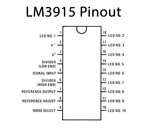
For a detailed description of pinout, dimension features, and specifications download the datasheet of LM3915
BC547 Pinout

For a detailed description of pinout, dimension features, and specifications download the datasheet of BC547
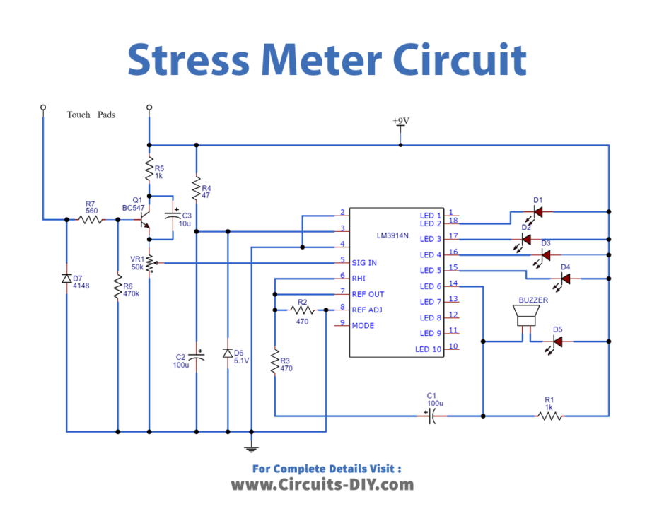
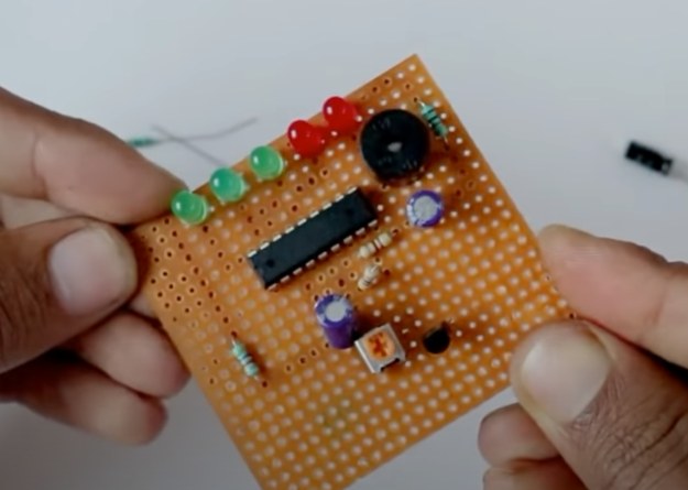
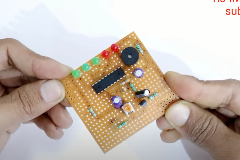
Stress Meter Circuit
Useful Steps
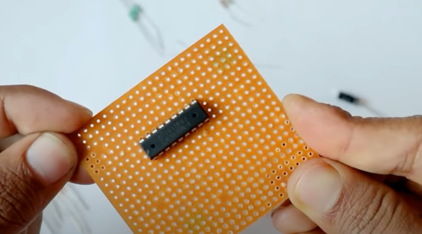
- Take your LM3915 IC and place it on your board
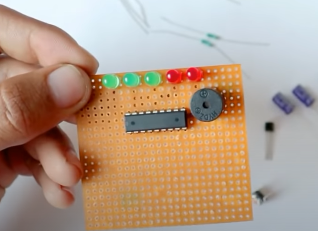
- Now join all the positive legs of LEDs together, while joining the negative legs to pins 18, 17, 16, 15, and 14 of an IC. Also, connect the buzzer in a way that its negative pin goes to pin 14 and the positive to the positive LEDs.
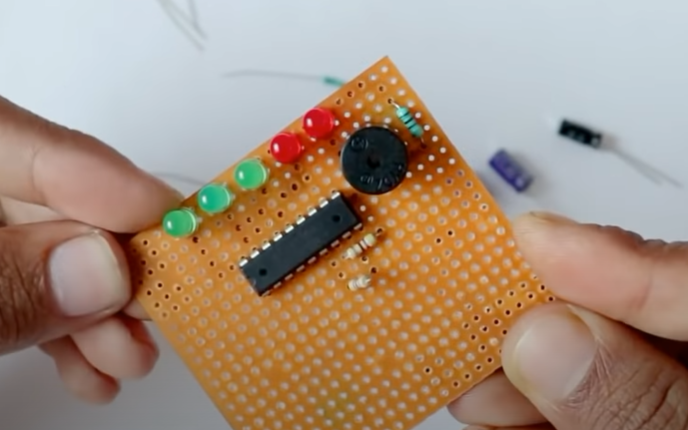
- Connect 1k resistor on buzzer negative to lead positively. After that, Connect the 470 ohms resistor to pin 8 to pins 6, and 7 of an IC. Connect another 470 ohms resistor to pin 6,7.
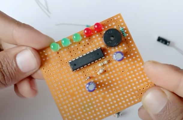
- Now, Connect the 100uf capacitor in a way that its positive goes to pin 14 of an IC, while the negative gets connected with that leg of the 470ohms resistor which got left ( the resistor whose one leg is connected to pin 6,7). To connect the Zener diode, connect its cathode leg to pin 3 and anode to pins 2, 4, and 8. Now connect another 100uf capacitor in a way that its positive goes on the cathode of Zener and negative to the anode of it.
- Then connect the 47ohms resistor to pin 3, Now to place the variable resistor, connect its middle pin to pin 5. Connect the emitter of transistor BC547 to preset 50K. Connect 1k resistor to the collector to lead positively.
- Now, connect the 10uf capacitor’s positive to the collector and the negative to the emitter. After that, connect the 470k resistor on pin 8 to the base of the transistor. Connect 4148 diodes to pin 8. we will connect The cathode to the touch plate.
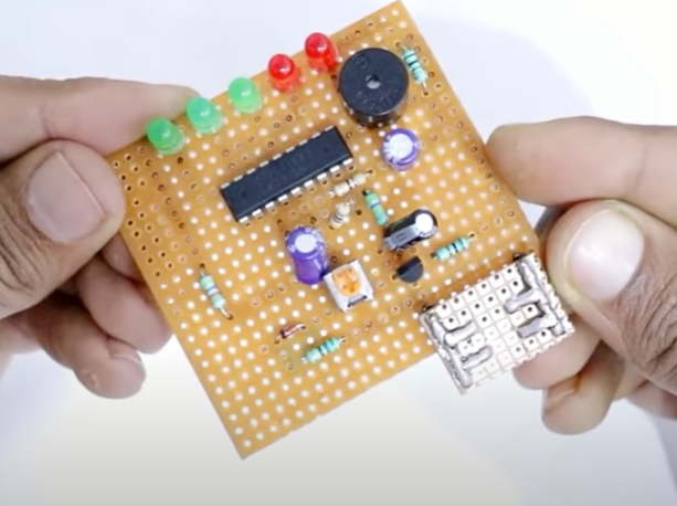
- Now, to make the touch plate use a very tiny Vero board and solder wire.
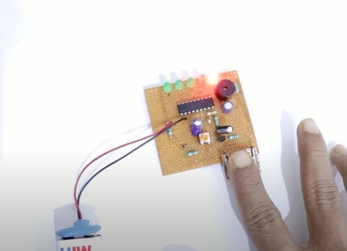
- It’s time to check the circuit.
Applications
- Medical devices.
- Lie detection devices, etc