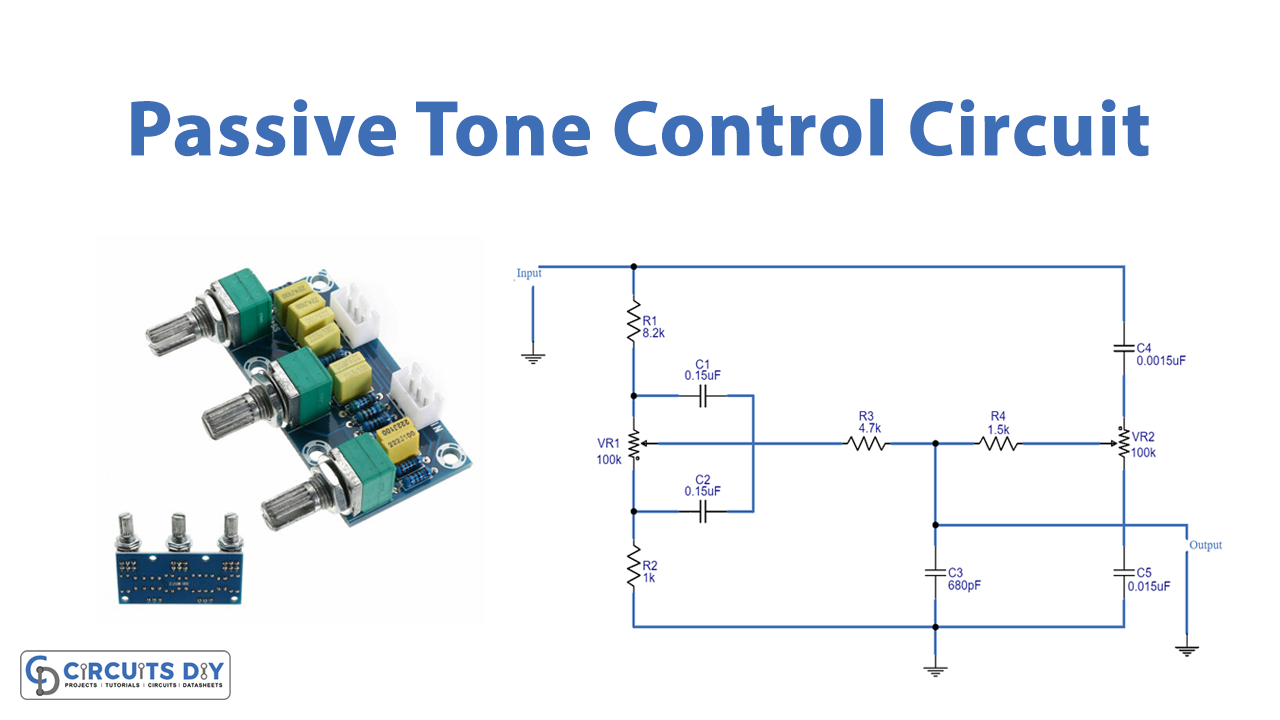
In this Tutorial, we are going to make a “Passive tone control circuit”. Tone control circuits are utilized by systems and devices to modify audio signals during recording or to regulate the bass response of speakers and headphones while listening. It is a circuit that includes the amplifiers and filters. The signal is filtered away by the filters, While amplifiers change signals before sending them to devices such as earphones and loudspeakers. The passive tone control circuit, without a doubt, is a circuit that does not require any additional power. As a result, it becomes cost-effective.
The circuit exclusively employs passive components such as resistors and capacitors. These capacitors alter the sound by boosting or reducing the cut-off frequencies. In a nutshell, it suppresses full-range signals while stimulating lower and higher sound signals.
Hardware Required
| S.no | Component | Value | Qty |
|---|---|---|---|
| 1. | Variable Resistor | 100K | 2 |
| 2. | Resistor | 8.2K,1K, 4.7K, 1.5K, 100K | 1, 1, 1, 1, 1 |
| 3. | Ceramic Capacitor | 0.0015uf, 0.015uf, 0.15uf, 680pf | 1, 1, 2, 1 |
Circuit Diagram
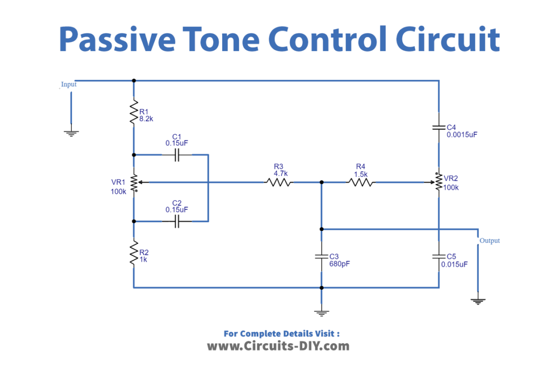
Working Explanation
When we apply an input signal to the circuit’s input. The audio signal will be received and separated in two ways. The first is the low pass filter. It consists of resistors R1, R2, and capacitors C1, and C2. It also offers the ability to change the lower frequencies ratio boost or the bass through the potentiometer VR1. The second path for a signal is the high-pass frequency filter section. It contains C4, R5, C5, and VR2, which may be modified for high frequency or treble. The signal from both the high and low-frequency filters is sent to the output through R3 and R4. Then, we have capacitor C3 to clean up the noisy signals before sending them out.
Application Uses
- Room acoustics
- Hearing devices
- Playback equipment