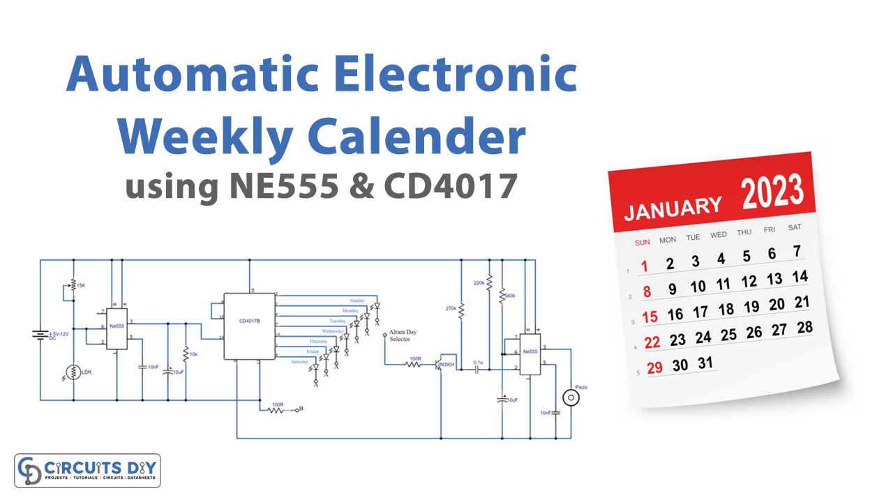
This is a very interesting circuit of an Automatic Electronic Weekly Calendar with Alarm. This circuit will show a visual indication of each day of the week by activating an LED. It can also work as an alarm on the selected day at sunrise. The duration of the alarm can also be increased or decreased as desired.
We are using two 555 timer ICs and one CD4017 decade counter IC. LDR is used as a light sensor and a Piezo buzzer is used for alarm purposes. You can convert this circuit into a weekly timer and a relay can be used in the place of the piezo buzzer to drive other AC/DC devices.
Hardware Components
The following components are required to make Electronic Weekly Calendar Circuit
| S.no | Component | Value | Qty |
|---|---|---|---|
| 1. | Breadboard | – | 1 |
| 2. | Electrolytic Capacitor | 10µF | 2 |
| 3. | Ceramic Capacitor | 10nF, 0.1µF | 2, 1 |
| 4. | Resistors | 10K, 100R, 270K, 220K, 560K | 1,2,1,1,1 |
| 5. | Transistor | 2N3904 | 1 |
| 6. | LDR | – | 1 |
| 7. | Decade Counter Divider IC | CD4017 | 1 |
| 8. | IC | NE555 Timer | 2 |
| 9. | Battery | 4.5-12V DC | 1 |
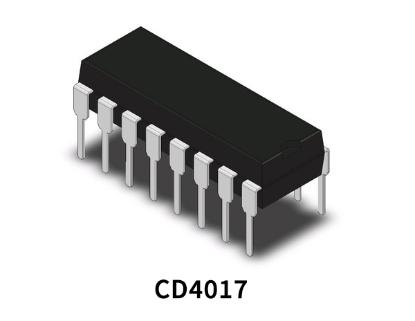
CD4017 Pinout
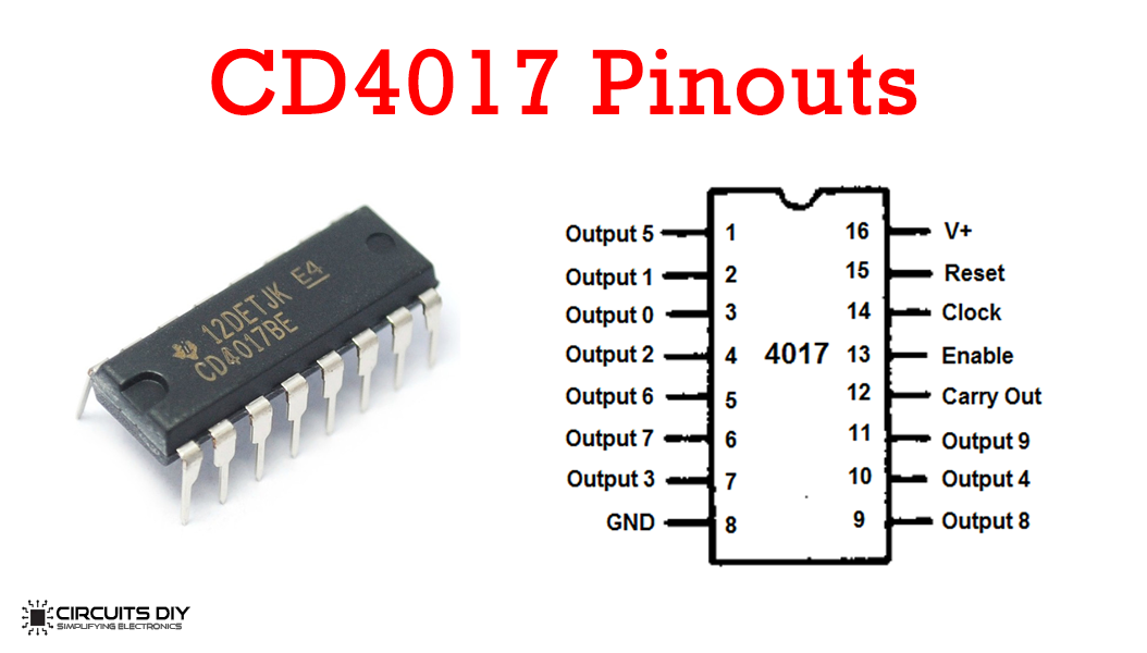
For a detailed description of pinout, dimension features, and specifications download the datasheet of CD4017
555 IC Pinout

For a detailed description of pinout, dimension features, and specifications download the datasheet of 555 Timer
Electronic Weekly Calendar Circuit
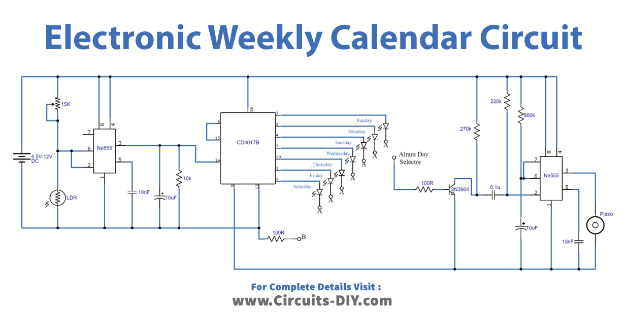
Working Explanation
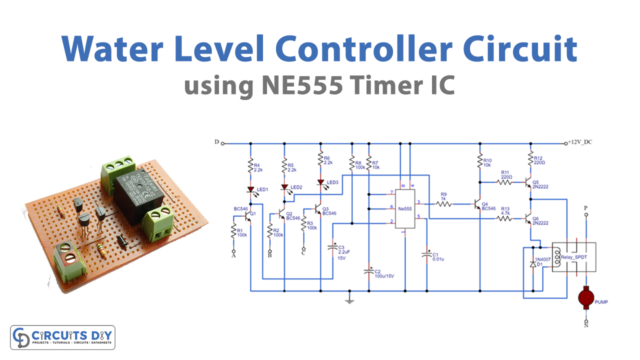
A light detector circuit is built around 555 timer IC1, and the output at pin 3 of this IC goes high during the day and low at night. Light is sensed through an LDR. A variable resistor of 15KΩ is used to adjust the sensitivity of detecting light.
IC2 is a decade counter IC, it has 10 outputs but we are only using 7 outputs for this circuit. An LED is connected at each output with the name of each day marked on it. This IC will activate a new LED and close the previous one each time when clock input (pin 14) goes from low to high.
The last part of this circuit is an alarm that is built around IC3 which is a 555 timer. It gives a beep for 10 seconds and then goes off automatically. You can increase or decrease the time period of alarm by increasing or decreasing the value of the capacitor Cx.
Connections:
- As you can see in the circuit diagram the point marked as the alarm day selector can be connected to any day’s output and the alarm will be set for that specific day.
- Connections marked A should be connected to mark B.
- Fit this finished circuit in a suitable casing and fix it at a place that gets sunlight or daylight. Make sure this circuit doesn’t get much light at night from any source to make this work efficiently.