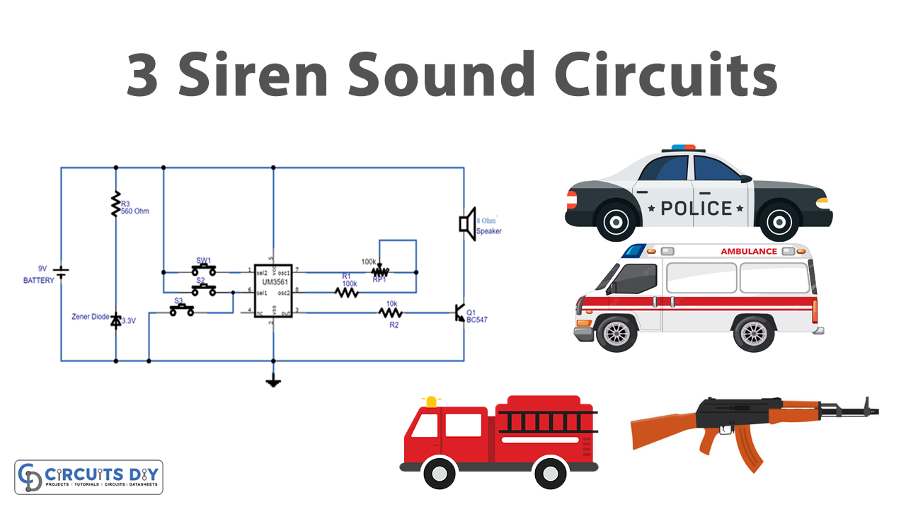
In this tutorial, we are going to make a “Three Siren Sound Generator Circuit Using UM3561”.
If you want to make a sound-based or alarm-based electronic project UM3561 IC is a good choice to select. UM3561 is an 8-pin low-power sound generator chip consisting of a programmed mask ROM and a tone generator. The tone generator produces different tones depending on the information written by the ROM. This particular IC contains a tone oscillator along with tune range hooks, it includes a programmed mask ROM to replicate the siren sound. That existing tone generator is capable of producing various types of musical tones through the oscillator clock and depending on the information written by the ROM. Here every single data saved in the ROM compares to every tone and this could be selected through the use of the address of the data location.
The standard working voltage of UM3561 is 3V and the Working Current is 150μA. The output current of UM3561 is 3mA. It’s a cheap IC primarily intended for toy vehicle purposes. As the IC consists of an oscillator along with selector stages, a sleek and stylish audio component could be designed with just a few extra parts. It can easily drive a magnetic speaker with a help of a single NPN transistor. This circuit can produce three different siren sounds (Police siren, Fire engine siren, and Ambulance siren), and can be utilized in several siren sound-based applications.
Hardware Components
The following components are required to make Siren Sound Generator Circuit
| S.no | Component | Value | Qty |
|---|---|---|---|
| 1. | IC | UM3561 | 1 |
| 2. | Transistor | BC547 | 1 |
| 3. | Variable Resistor | 100KΩ | 1 |
| 4. | Resistor | 560Ω, 100KΩ, 10KΩ | 1,1,1 |
| 5. | Zener Diode | 3.3V | 1 |
| 6. | Push Button Switch | – | 3 |
| 7. | Speaker | 8Ω | 1 |
| 8. | Connecting Wires | – | – |
| 9. | Battery | 9V | 1 |
UM3561 Pinout
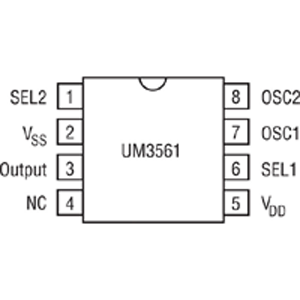
For a detailed description of pinout, dimension features, and specifications download the datasheet of UM3561
Siren Sound Generator Circuit

Working Explanation
As we can see the main part of this circuit is UM3561 IC, it can intake 3 to 5V as a power supply and gives an output range of -3.0V to +3.0V. Here we power the whole circuit with a 9V battery. So, to regulate the battery voltage Zener diode (3.3V) is used across bias lines. Pins Sel1 and sel2 are connected with three pushes to the ON switch. The output pin is connected to the 8Ω speaker through an NPN transistor. to maintain oscillation, oscillator pins 7, and 8 are connected with variable Resistor VR1 and R1. The UM3561 has sound effect ROM and it is organized as 256 words by 8 bits. By applying this bias to the SEL pins we can get the different siren sound effects. As UM3561 IC generates a multitone output signal. Pin7 and piN8 are used to control the frequency of the internal oscillator by connecting an external resistor between these two pins, we have connected R1=100 kΩ and variable resistor VR1=100 kΩ. These oscillations are then transferred to the control circuit which selects a tone based on the inputs of pin6 and pin2 select pins. Then the control circuit will pass this signal to the address counter and from the address counter to ROM and then to an output pin. An NPN transistor is usually connected at the output to amplify the sound since the sound signal produced is very weak.
Now if we want to generate an ambulance siren sound then we have to press the switch S1, for the fire bridge siren the switch S2 should be pressed, and for the machine gun siren sound to be generated at the output, the switch S3 should be pressed. When there is no switch pressed then the police siren will generate at the output pin.
Applications
- Sounds-based toys applications
- Alarm
- Also used in the sirens of law enforcement & medical (EMT) vehicles such as police cars & ambulances respectively.