Introduction
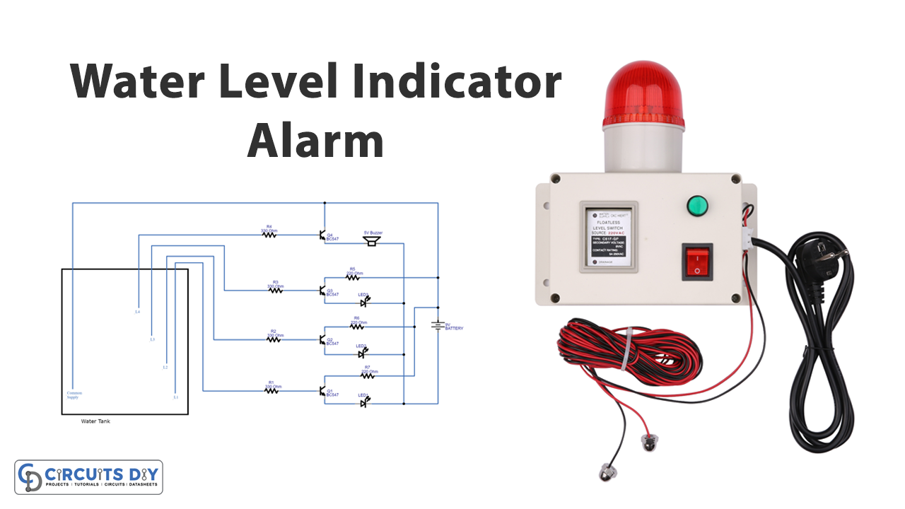
The water level indicator is very useful yet easy to make. Practically, used for the measurement of water. We can make the circuit in so many ways using a microcontroller and other programming chips. But, since we aim to provide simple projects that would use fewer components and can be easily assembled on the PCB Board. Therefore, we will use transistors for this project. This three-terminal element is easy to handle on any circuit board. So, in this tutorial, we are going to “Water Level Indicator Alarm”
A Water level indicator is a simple electronic circuit that can show the level of any liquid in a vessel such as a tank, pool, or container. There are several electronic configurations available for achieving this function. Here, we will follow a simple transistor switching technique.
Hardware Components
The following components are required to make Water Level Indicator Circuit
| S.o | Component | Value | Qty |
|---|---|---|---|
| 1. | Transistor | BC547 | 4 |
| 2. | Buzzer | – | 1 |
| 3. | LED | – | 4 |
| 4. | Resistor | 330Ω, 220Ω | 4,3 |
| 5. | Battery | 9V | 1 |
| 6. | 2-Pin Connector | – | 1 |
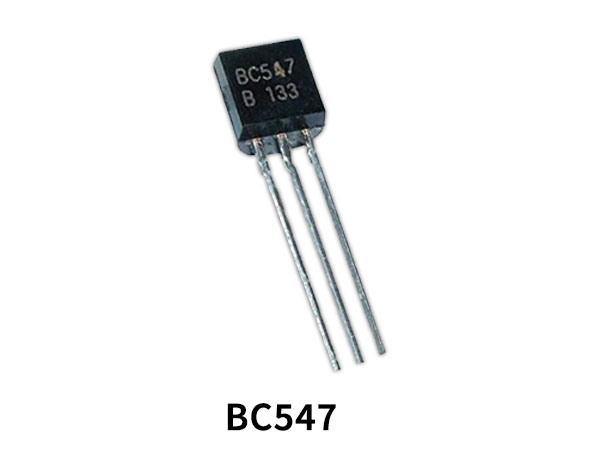
BC547 Pinout

For a detailed description of pinout, dimension features, and specifications download the datasheet of BC547
Water Level Indicator Circuit
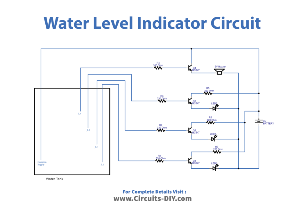
Working Explanation
The working of this Water Level Indicator is pretty simple, we attached four terminals fashioned from the exposed end of wires at some heights in the vessel, tank, reservoir, etc. When you fill the water in, each LED starts to regarding the terminal in contact with the water, which sends a control signal to the base of each BC547. The resultant collector output triggers the LED to glow showing the current level of the water in the vessel.
Application and Uses
- To control the water level.
- In irrigation systems.
- Oil tank level control systems.
- Automatic pumps, etc.