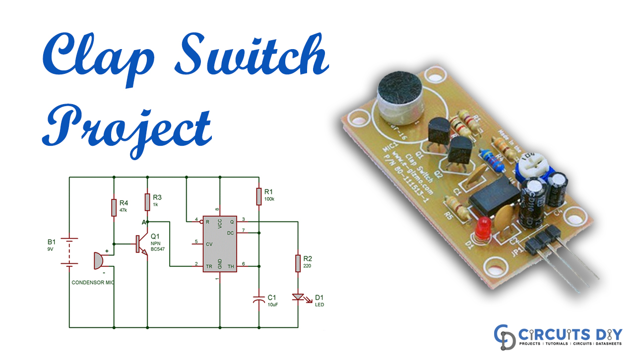
A Clapping switch is a fascinating DIY project circuit that turns ON/OFF the LED lights with a specific pitch’s solid clap sound. However, this applauds or clap switch circuit’s primary segment is the Electric Condenser Mic, which utilizes here as a sound sensor.
Moreover, the condenser Mic fundamentally converts sound energy into electrical energy. It is likewise used to trigger the NE555 timer IC through a Transistor. Also, setting off the NE555 IC would turn ON the LED, automatically turning OFF after some time.
I have made this circuit as simple as could be expected under the limited budget. You can explore numerous complex Clap switch circuits (utilizing 555 IC) that perform the same function in other tutorials.

Hardware Components
The following components are required to make Clap Switch Circuit
| S.no | Component | Value | Qty |
|---|---|---|---|
| 1. | Condenser Mic | – | 1 |
| 2. | IC | 555 Timer | 1 |
| 3. | Transistor | BC547 | 1 |
| 4. | Resistor | 1K, 47K, 100K, 220 | 1, 1, 1, 1 |
| 5. | Capacitor | 10uF | 1 |
| 6. | LED | – | 1 |
| 7. | Battery and Battery Snap Connector | 5-9V | 1 |
| 8. | Breadboard | – | 1 |
NE555 IC Pinout

For a detailed description of pinout, dimension features, and specifications download the datasheet of NE555 IC
Clap Switch Circuit
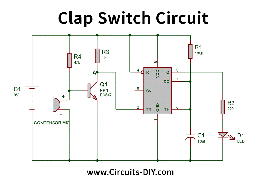
Circuit Operation
Subsequently, you can see the circuits and their respective component connections in the above schematic of the clap switches above schematic. At first, the semiconductor is in an OFF state because there isn’t sufficient (0.7 Volts) base-producer voltage to turn it ON. Here, point An is at high potential, and likewise, it is associated with Trigger pin 2 of 555 IC. Thus Trigger pin 2 is likewise at high potential. Therefore, to trigger the 555 IC through Trigger PIN 2, the voltage of the PIN 2 must be beneath Vcc/3. So at this stage, LED is OFF.
Henceforth, when we produce some solid sound close to the condenser mic, this sounds energy converts into electrical energy, and it will raise the potential at the Base, which will turn the Transistor ON. When the semiconductor becomes ON, Point A’s potential will turn out to be LOW, and it will trigger the 555 IC due to the low voltage (underneath Vcc/3) at Trigger Pin 2, and the LED will turn ON. We have associated the LED to Output PIN 3 of 555 IC through a 220ohm resistor.
After some time, LED will be automatically turned OFF. Therein, we are utilizing the 555 timer IC in Monostable Mode. However, the LED will stay turned ON for 1.1*R1*C1 seconds. With this formula, we can see that we can change its ON and OFF time by changing the estimation of Resistor R1 or/and Capacitor C1. We can alter this circuit utilizing Relay to control the Electronic appliances (120/220V AC). Control PIN 5 of 555 Timer IC ought to be associated with Ground through a 0.01uF capacitor.
Applications and Uses
The Clap switch is not only used to turn the LED ON and OFF. Yet, it may be utilized in many electric appliances, for example, Tube Light, Fan, Radio, or whatever another essential circuit you need to turn ON by a Sound signal.