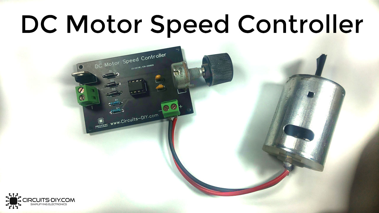
Directional & speed control (RPM) for AC/DC Motors can be achieved through various methods. It is essential to be able to control the speed & direction of DC drives in industries such as textile, mechanical & electrical for a number of factory processes. In this article, we will take a look at how you can easily design a PWM DC Motor Controller with a NE555 timer IC using & a small number of other components.
PWM (Pulse Width Modulation) is an analog control technique through which we can generate a variable square wave signal, by turning on and off the power going to any electronic device at a fast rate. The average voltage depends on the duty cycle of the signal. Here, the NE555 precision timer IC is running in the astable mode in order to generate a free-running PWM signal. You can check our previous article on astable multivibrators to learn more about their operation.
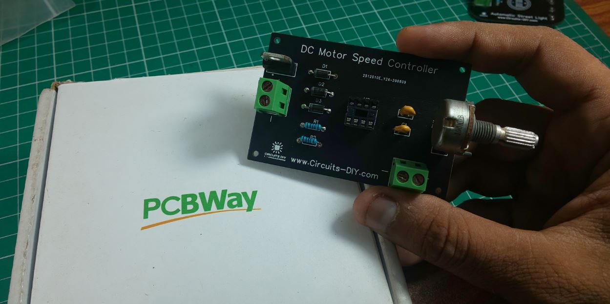
PCBWay commits to meeting the needs of its customers from different industries in terms of quality, delivery, cost-effectiveness, and any other demanding requests. As one of the most experienced PCB manufacturers in China. They pride themselves to be your best business partners as well as good friends in every aspect of your PCB needs.
Hardware Components
You will need the following parts to build this project
| S.no | Component | Value | Qty |
|---|---|---|---|
| 1. | DC Motor | 12V/6000 – 10000RPM | 1 |
| 2. | PWM DC Motor Controller PCB | PCBWay | 1 |
| 3. | IC | NE555 Timer | 1 |
| 4. | Darlington Transistor | TIP122/NPN | 1 |
| 5. | Potentiometer | 100K | 1 |
| 6. | Diode | 1N4007 | 3 |
| 7. | Capacitor | 100nF | 2 |
| 8. | Resistor | 1K | 2 |
| 9. | Soldering Iron | 45W – 65W | 1 |
| 10. | Soldering Wire with Flux | – | 1 |
| 11. | DC Battery | 12V | 1 |
| 12. | Battery Clips | – | 1 |
| 13. | Soldering Stand | – | 1 |
| 14. | Jumper Wires | – | As per need |
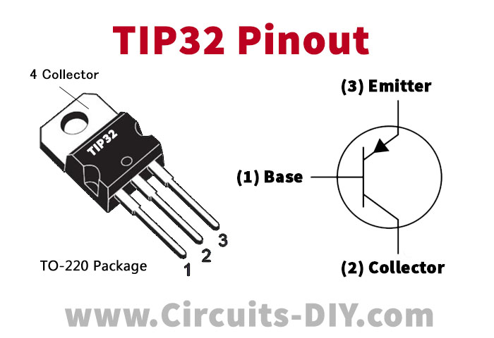
TIP122 Pinout
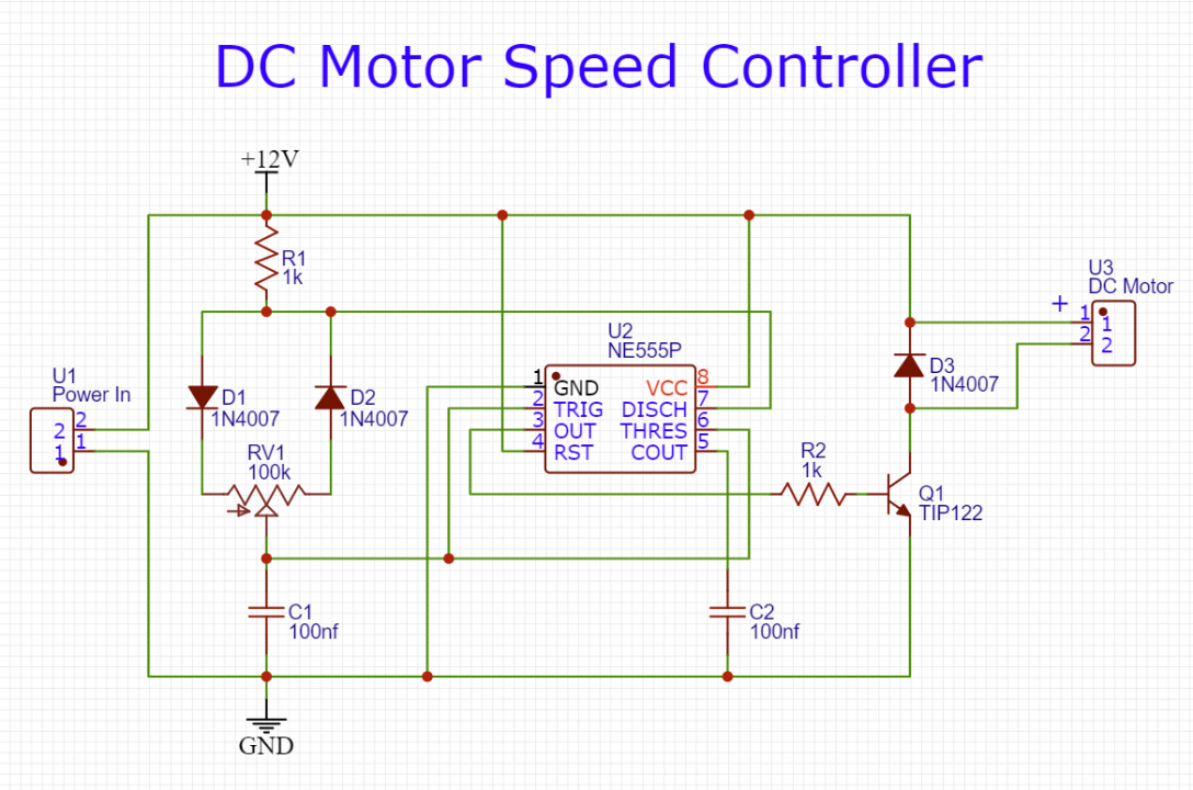
Circuit Diagram
Working Explanation
The working of the circuit is as follows, the 555 timer IC is configured to operate in astable multivibrator mode, producing a free-running square wave (PWM). A 100K pot is used to control the time period of the duty cycle of the 555 timers, effectively controlling the speed of the motor. The control terminal of the timer IC is connected to a 100nF capacitor to remove an external noise from the terminal. The active-low reset pin 4 is connected to the Vcc of the circuit in order to prevent unwanted reset of the output.
If the motor you want to control exceeds the 555 timer output current sink/source rating of 200mA, you can use a Darlington pair transistor/MOSFET (TIP122) to drive the DC motor as it can handle currents up to 5A. Also, use a flyback diode (1N4007) in parallel to the motor in order to prevent any voltage spikes.