Introduction
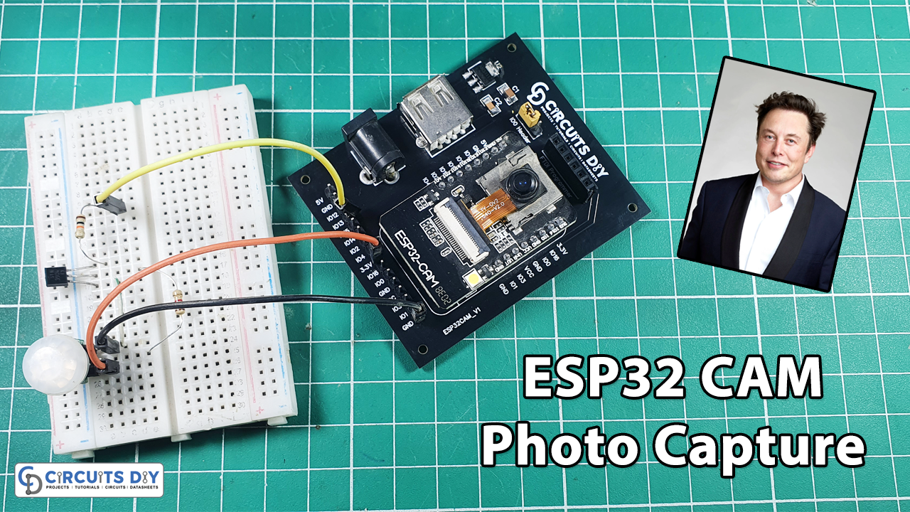
In this project, we’re going to make a motion sensor detector with photo capture using an ESP32-CAM. When your PIR sensor detects motion, it wakes up, takes a photo, and saves it on the microSD card.
This Project is sponsored by PCBWay. They have an open-source community, people can share their design projects with each other. Moreover, every time people place an order for your board, PCBWay will donate 10% of the cost of PCB to you, for your contribution to the Open Source Community.
Hardware Components
You will require the following hardware for making PIR Motion Detector with Image Capture using ESP32-CAM.
| Sr No | Components | Value | Qty |
|---|---|---|---|
| 1 | ESP32 CAM | – | 1 |
| 2 | DC Power for ESP32 CAM | – | 1 |
| 3 | PIR Motion Sensor | – | 1 |
| 4 | Transistor | 2N3904 | 1 |
| 5 | Resistor | 1KΩ,1KΩ | 1,1 |
| 6 | Breadboard | – | 1 |
| 7 | Jumper Wires | – | 1 |
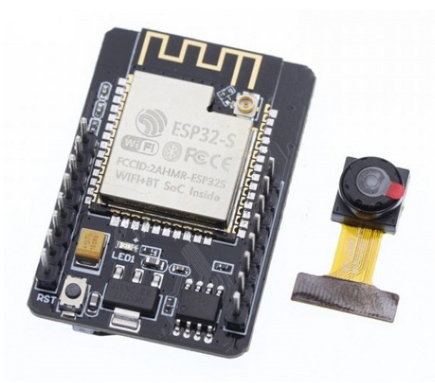
ESP32-CAM Specifications
The ESP32-CAM is based on the ESP32-S module, so it shares the same specifications. It has the following features:
- 802.11b/g/n Wi-Fi
- Bluetooth 4.2 with BLE
- UART, SPI, I2C, and PWM interfaces
- Clock speed up to 160 MHz
- Computing power up to 600 DMIPS
- 520 KB SRAM plus 4 MB PSRAM
- Supports WiFi Image Upload
- Multiple Sleep modes
- Firmware Over the Air (FOTA) upgrades possible
- 9 GPIO ports
- Built-in Flash LED
Camera Specifications
The ESP32-CAM includes an OV2640 camera module. The device also supports OV7670 cameras. The OV2640 has the following specifications:
- 2 Megapixel sensor
- Array size UXGA 1622×1200
- Output formats include YUV422, YUV420, RGB565, RGB555 and 8-bit compressed data
- Image transfer rate of 15 to 60 fps
Steps Making PIR Motion Detector with Image Capture
Formatting MicroSD Card
The first thing we recommend doing is formatting your microSD card. You can use the Windows formatting tool or any other microSD formatting software.

Schematic
Make connections according to the circuit diagram given below.

Installing Arduino IDE
First, you need to install Arduino IDE Software from its official website Arduino. Here is a simple step-by-step guide on “How to install Arduino IDE“.
Installing the ESP32 Board in Arduino IDE
After the Installation of Arduino IDE, There’s an add-on that allows you to program the ESP32 using the Arduino IDE. Here is a simple guide on “How to Install ESP32 on Arduino IDE“.
ESP32-CAM Upload Code
To upload code to the ESP32-CAM board, connect it to your computer using an FTDI programmer. Follow the next schematic diagram:

Code
Now copy the following code and upload it to Arduino IDE Software.
We modified this project from Randomnertutorials. You can check the original source for a detailed description. All Credit to Rui Santos
/*********
  Rui Santos
  Complete project details at https://RandomNerdTutorials.com/esp32-cam-pir-motion-detector-photo-capture/

  IMPORTANT!!!
   - Select Board "AI Thinker ESP32-CAM"
   - GPIO 0 must be connected to GND to upload a sketch
   - After connecting GPIO 0 to GND, press the ESP32-CAM on-board RESET button to put your board in flashing mode

  Permission is hereby granted, free of charge, to any person obtaining a copy
  of this software and associated documentation files.
  The above copyright notice and this permission notice shall be included in all
  copies or substantial portions of the Software.
*********/

#include "esp_camera.h"
#include "Arduino.h"
#include "FS.h"                // SD Card ESP32
#include "SD_MMC.h"            // SD Card ESP32
#include "soc/soc.h"           // Disable brownour problems
#include "soc/rtc_cntl_reg.h"  // Disable brownour problems
#include "driver/rtc_io.h"
#include <EEPROM.h>            // read and write from flash memory
// define the number of bytes you want to access
#define EEPROM_SIZE 1

RTC_DATA_ATTR int bootCount = 0;

// Pin definition for CAMERA_MODEL_AI_THINKER
#define PWDN_GPIO_NUM     32
#define RESET_GPIO_NUM    -1
#define XCLK_GPIO_NUM      0
#define SIOD_GPIO_NUM     26
#define SIOC_GPIO_NUM     27
#define Y9_GPIO_NUM       35
#define Y8_GPIO_NUM       34
#define Y7_GPIO_NUM       39
#define Y6_GPIO_NUM       36
#define Y5_GPIO_NUM       21
#define Y4_GPIO_NUM       19
#define Y3_GPIO_NUM       18
#define Y2_GPIO_NUM        5
#define VSYNC_GPIO_NUM    25
#define HREF_GPIO_NUM     23
#define PCLK_GPIO_NUM     22

int pictureNumber = 0;

void setup() {
  WRITE_PERI_REG(RTC_CNTL_BROWN_OUT_REG, 0); //disable brownout detector
  Serial.begin(115200);

  Serial.setDebugOutput(true);

  camera_config_t config;
  config.ledc_channel = LEDC_CHANNEL_0;
  config.ledc_timer = LEDC_TIMER_0;
  config.pin_d0 = Y2_GPIO_NUM;
  config.pin_d1 = Y3_GPIO_NUM;
  config.pin_d2 = Y4_GPIO_NUM;
  config.pin_d3 = Y5_GPIO_NUM;
  config.pin_d4 = Y6_GPIO_NUM;
  config.pin_d5 = Y7_GPIO_NUM;
  config.pin_d6 = Y8_GPIO_NUM;
  config.pin_d7 = Y9_GPIO_NUM;
  config.pin_xclk = XCLK_GPIO_NUM;
  config.pin_pclk = PCLK_GPIO_NUM;
  config.pin_vsync = VSYNC_GPIO_NUM;
  config.pin_href = HREF_GPIO_NUM;
  config.pin_sscb_sda = SIOD_GPIO_NUM;
  config.pin_sscb_scl = SIOC_GPIO_NUM;
  config.pin_pwdn = PWDN_GPIO_NUM;
  config.pin_reset = RESET_GPIO_NUM;
  config.xclk_freq_hz = 20000000;
  config.pixel_format = PIXFORMAT_JPEG;

  pinMode(4, INPUT);
  digitalWrite(4, LOW);
  rtc_gpio_hold_dis(GPIO_NUM_4);

  if(psramFound()){
    config.frame_size = FRAMESIZE_UXGA; // FRAMESIZE_ + QVGA|CIF|VGA|SVGA|XGA|SXGA|UXGA
    config.jpeg_quality = 10;
    config.fb_count = 2;
  } else {
    config.frame_size = FRAMESIZE_SVGA;
    config.jpeg_quality = 12;
    config.fb_count = 1;
  }

  // Init Camera
  esp_err_t err = esp_camera_init(&config);
  if (err != ESP_OK) {
    Serial.printf("Camera init failed with error 0x%x", err);
    return;
  }

  Serial.println("Starting SD Card");

  delay(500);
  if(!SD_MMC.begin()){
    Serial.println("SD Card Mount Failed");
    //return;
  }

  uint8_t cardType = SD_MMC.cardType();
  if(cardType == CARD_NONE){
    Serial.println("No SD Card attached");
    return;
  }

  camera_fb_t * fb = NULL;

  // Take Picture with Camera
  fb = esp_camera_fb_get();
  if(!fb) {
    Serial.println("Camera capture failed");
    return;
  }
  // initialize EEPROM with predefined size
  EEPROM.begin(EEPROM_SIZE);
  pictureNumber = EEPROM.read(0) + 1;

  // Path where new picture will be saved in SD Card
  String path = "/picture" + String(pictureNumber) +".jpg";

  fs::FS &fs = SD_MMC;
  Serial.printf("Picture file name: %s\n", path.c_str());

  File file = fs.open(path.c_str(), FILE_WRITE);
  if(!file){
    Serial.println("Failed to open file in writing mode");
  }
  else {
    file.write(fb->buf, fb->len); // payload (image), payload length
    Serial.printf("Saved file to path: %s\n", path.c_str());
    EEPROM.write(0, pictureNumber);
    EEPROM.commit();
  }
  file.close();
  esp_camera_fb_return(fb);

  delay(1000);

  // Turns off the ESP32-CAM white on-board LED (flash) connected to GPIO 4
  pinMode(4, OUTPUT);
  digitalWrite(4, LOW);
  rtc_gpio_hold_en(GPIO_NUM_4);

  esp_sleep_enable_ext0_wakeup(GPIO_NUM_13, 0);

  Serial.println("Going to sleep now");
  delay(1000);
  esp_deep_sleep_start();
  Serial.println("This will never be printed");
}

void loop() {

}
Working Explanation
Here is a quick overview of how the project works.
- The ESP32-CAM is in deep sleep mode with external wake-up enabled.
- When motion is detected, the PIR motion sensor sends a signal to wake up the ESP32.
- The ESP32-CAM takes a photo and saves it on the microSD card.
- It goes back to deep sleep mode until a new signal from the PIR motion sensor is received.
Applications
- Security Systems
- Shops, Mall, Banks & Companies, etc
Conclusion.
We hope you have found this PIR Motion Detector with Photo Capture using ESP32-CAM very useful. If you feel any difficulty in making it feel free to ask anything in the comment section.