In this tutorial, we are going to demonstrate a project, “Fire Alarm.” In modern buildings and architecture, fire alarms are the most critical necessities, especially in banks, data centers, and gas stations.
They sense fires in the atmosphere very early on by feeling smoke and heat, warning people about the fire, and having adequate time to take precautionary steps. Not only can it stop huge casualties from lethal flames, but it also proves to be life-saving. Here, we create an alarm system using the 555 Timer IC that detects the fire, which is the temperature rise in the area, and triggers the alarm.

Hardware Components
The following components are required to make a Fire Alarm Circuit
| S. No | Component | Value | Qty |
|---|---|---|---|
| 1. | IC | NE555 Timer | 1 |
| 2. | Battery | 9V | 1 |
| 3. | NPN Transistor | BC547 | 1 |
| 4. | Buzzer | – | 1 |
| 5. | Capacitor | 10uF | 1 |
| 6. | Resistor | 1K, 100K, 4.7K | 1 |
| 7. | Thermistor | 10K | 1 |
| 8. | Variable resistor | 1M | 1 |
NE555 IC Pinout

For a detailed description of pinout, dimension features, and specifications download the datasheet of 555 Timer
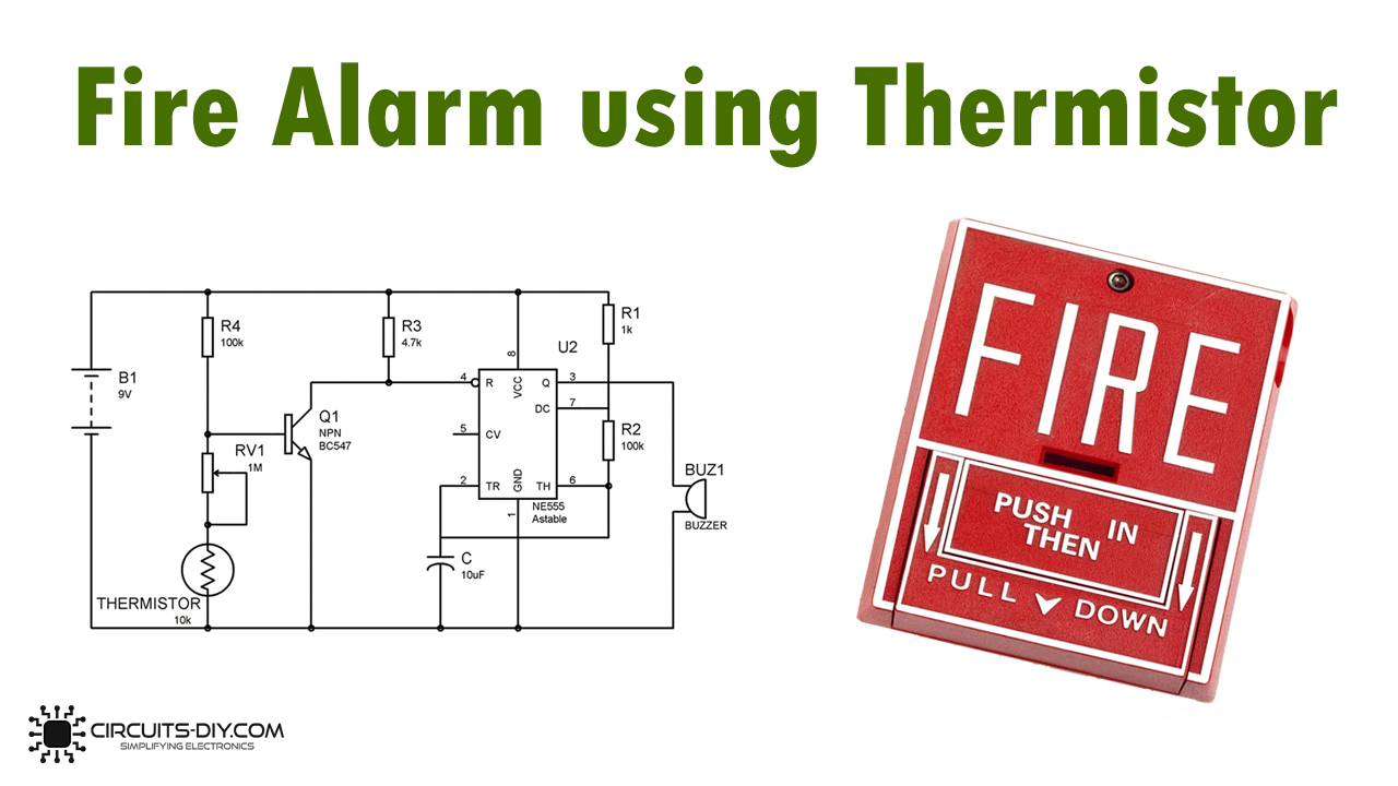
Fire Alarm Circuit
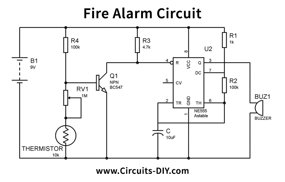
Working Explanation
The fire alarm diagram can be seen in the figure above. If no FIRE occurs, the thermistor will remain at 10 K. And transistor is left in ON since the base-emitter of the transistor has sufficient voltage, rendering it ON. Pin 4 (RESET) will be attached to the ground when the transistor will be on, and the 555 timer IC will not work when the reset pin is ground.
Now that we start heating the thermistor by Fire, its resistance begins to decline, and as its resistance declines, the strain at the base of the Transistor starts to decrease. If the voltage is short of the working voltage of the transistor, then the transistor is OFF. And when the transistor becomes OFF, the 555-timer IC reset pin gets positive voltage through R3, and the 555 timer IC begins to operate and beeps a buzzer.
Usually, the voltage of 0.7V in the transistor is required in the base and emitter to turn it on. We must also carefully change the value of the RV1 and thermistor variable resistance for the circuit to operate properly. To do this, detach the thermistor and allow RV1 to be grounded, change the RV1 to the point that the Buzzer begins with even a slight RV1 turn. In other words, Buzzer begins to beep if the resistance decreases even a little. Associate the thermistor again at this point.
Applications and Uses
The applications and uses of fire alarm circuits are to detect fire and are commonly used in
- Banks
- Data centers
- Gas stations