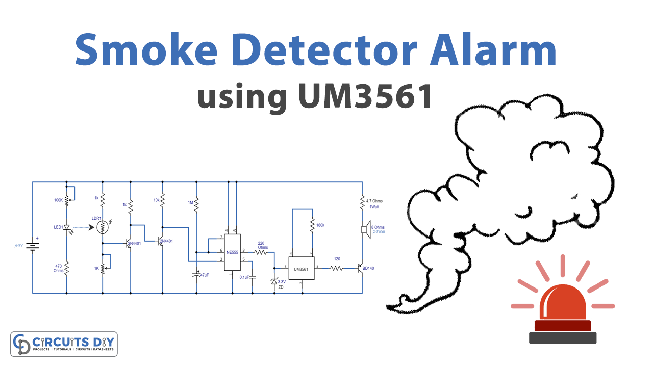
Here is a very interesting project on a Smoke detector circuit. It can detect the smoke in the atmosphere which can be produced as a result of something burning. This circuit can also be called an optical smoke detector because it uses an LED and an LDR for sensing the smoke.
This project comprises a circuit divided into three parts. The first part is a dark detector circuit built around two transistors. The second part is a timer circuit built around a 555 timer IC and the final stage is an alarm circuit using a melody generator IC UM3651.
Hardware Components
Smoke Detector Alarm Circuit
| S.no | Component | Value | Qty |
|---|---|---|---|
| 1. | Input Supply DC | 6-9V | 1 |
| 2. | Transistor | 2N4401, BD140 | 2, 1 |
| 3. | LDR | – | 1 |
| 4. | LED | – | 1 |
| 5. | IC | NE555 Timer, UM3561 | 1 |
| 6. | Speaker | 8Ω | 1, 1 |
| 7. | Resistor | 470Ω,1KΩ,,10KΩ,1MΩ,220Ω,180KΩ,120Ω, 4.7Ω/1W | 1 |
| 8. | Variable Resistor | 1KΩ, 100KΩ | 1, 1 |
| 9. | Capacitor | 47µF, 0.1µF | 1, 1 |
| 10. | Zener diode | 3.3V | 1 |
UM3561 Pinout
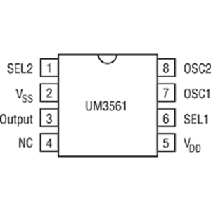
For a detailed description of pinout, dimension features, and specifications download the datasheet of UM3561
Smoke Detector Alarm Circuit
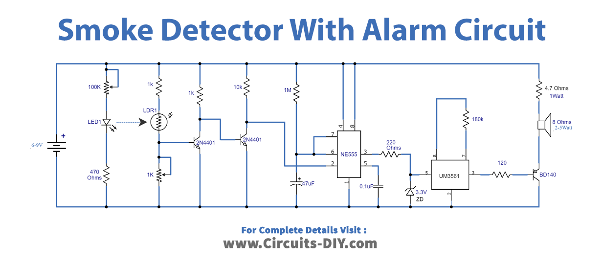
Working Explanation
The working of this circuit is explained here simply. When the light of the LED will be continuously falling onto the LDR from a small distance of a few inches, so if any type of smoke crosses between the LED and the LDR the resistance of LDR will increase due to which transistor Q1 will switch off while Q2 will switch on. Q2 will trigger the 555 timer IC and its output goes high for a preset time period which activates the UM3561 alarm IC. As a result, a loud alarm will be produced. the alarm will stop after the preset time period is over. To adjust the sensitivity of this circuit we have used two variable resistors, the 100K variable resistor will control the brightness of the LED and the 1K variable resistor is used to adjust the sensitivity of the LDR.