Introduction
Do you love tinkering with electronics and creating unique gadgets? If so, you’ll love this simple music box circuit that can be quickly built with just a few components. Using the popular 555 and CD4017 integrated circuits, this circuit allows you to create custom melodies with up to 10 notes. The circuit design is straightforward, making it perfect for beginners or those experimenting with electronics.
With the ability to adjust the clock rate and modify the spaces of silence between notes, this music box circuit provides endless possibilities for creating unique and beautiful melodies. So why not give it a try and see what kind of melodies you can create?
Hardware Required
| S no | Components | Value | Qty |
|---|---|---|---|
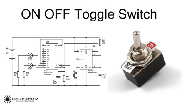
| 1 | IC | IC1 = IC2: NE555 timer IC3 = CD4017 | 2 1 |
| 2 | Non Polar Capacitor | C2: 10nF | 1 |
| 3 | Resistor | R1 = R2: 33K resistor R3 = R5 = R9: 10K resistors R4 = R7 = R10: 15K resistors R6 = R8: 22K resistors R11 = 470 ohm resistor | 2 3 3 2 1 |
| 4 | Polar capacitor | C1: 10uF/25V | 1 |
| 5 | Transistor | Q1: TIP29 | 1 |
| 6 | Diode | D1…D8 = 1N4148 | 8 |
| 7 | Battery | 6V | 1 |
| 8 | Speaker | 8 OHM | 1 |
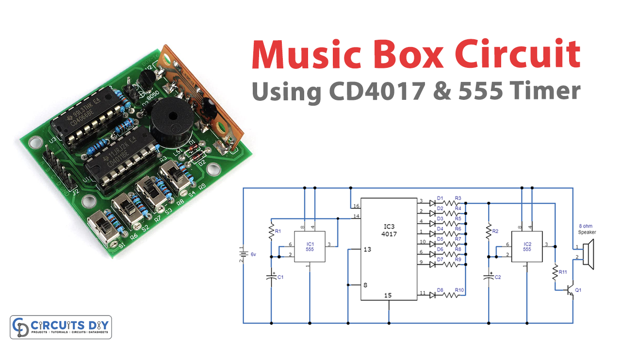
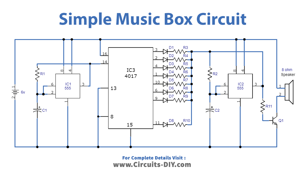
Circuit Diagram
Working Explanation
Power Source
A 9V PP3 battery or a 9-volt AC/DC adapter can power the music box circuit.
Clock Generation
The left 555 is a clock generator for the 4017 decade counter. The clock rate can be modified and adjusted by adjusting the value of resistor R1 or by using a potentiometer with a 50K value and a 1K series resistor. This changes the speed of the 4017 output sequence and creates the musical sounds of the box.
Clock Input to CD4017
The output signal from the 555 provides the clock input of the CD4017, which produces ten active outputs sequentially, starting with 0 and ending at junction 9.
Second 555 IC
Each CD4017 output is wired to a series diode and resistor pair, which connects the corresponding resistor in series with the 555’s second resistor, R2. Together with capacitor C2, this configuration ensures that the second 555 will oscillate at the specified frequency. Right-hand 555 oscillates at a frequency determined by the set resistor (of the 4017 outputs) in combination with R2 and C2.
Speaker Operation
For the speaker to work, transistor Q1 must operate above the saturation cutoff frequency ranges for which the second 555 is set. The diodes and the resistors in series should be tested with various values. Also, the other pins of the 4017’s outputs can be left unconnected or chosen randomly, allowing you to experiment with and modify the size and placement of the silences.
Conclusion
In conclusion, the simple music box circuit is a fun and easy-to-build project. This circuit is a great way to explore the world of electronics and music.
We hope you enjoyed learning about this circuit and feel inspired to try building it yourself. With just a few components and some basic knowledge of electronics, you can create your unique melodies. So try it – who knows what kind of beautiful music you can create!