
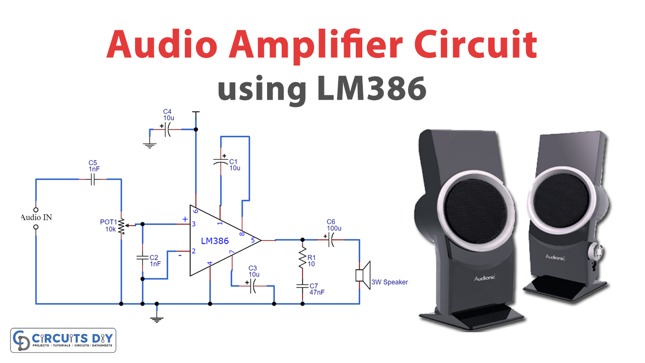
The Audio amplifier is the basic circuit configuration that is required to amplify, the audio signal received through a device like a microphone or the audio signal that is to be transmitted out through a speaker/ Radio device/Wireless transmitter, etc.
Audio Amplifier circuits have so many practical applications like communications, Radio wave transmitters, Hi-fi devices, Home audio systems, talking toys, Robots, and even in the military as acoustic weapons. So today in this tutorial we are going to make a simple cost effective “Audio Amplifier circuit using LM386 IC“
Hardware Components
The following components are required to make Audio Amplifier Circuit
| S.No | Component | Value | Qty |
|---|---|---|---|
| 1. | Breadboard | – | 1 |
| 2. | Battery | 9v | 1 |
| 3. | Connecting Wires | – | 1 |
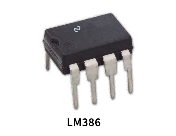
| 4. | Op-Amp IC | LM386 | 1 |
| 5. | Electrolytic Capacitor | 10uF, 100uF | 3,1 |
| 6. | Ceramic Capacitor | 1nF, 47nF | 2, 1 |
| 7. | Potentiometer | 10k | 1 |
| 8. | Resistor | 10 ohms | 1 |
| 9. | Speaker | 8 ohm | 1 |
LM386 Pinout
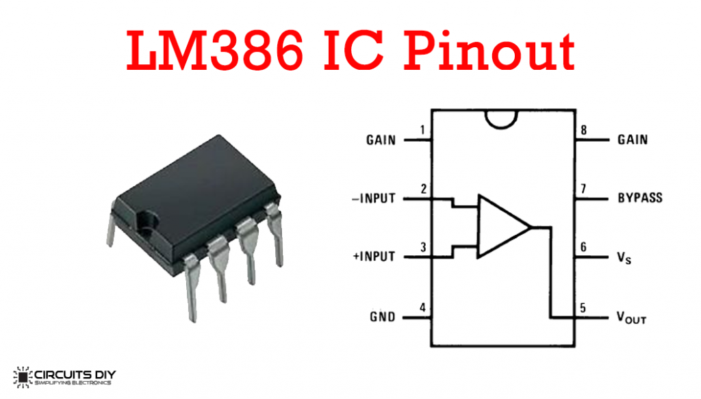
For a detailed description of pinout, dimension features, and specifications download the datasheet of LM386
Audio Amplifier Circuit
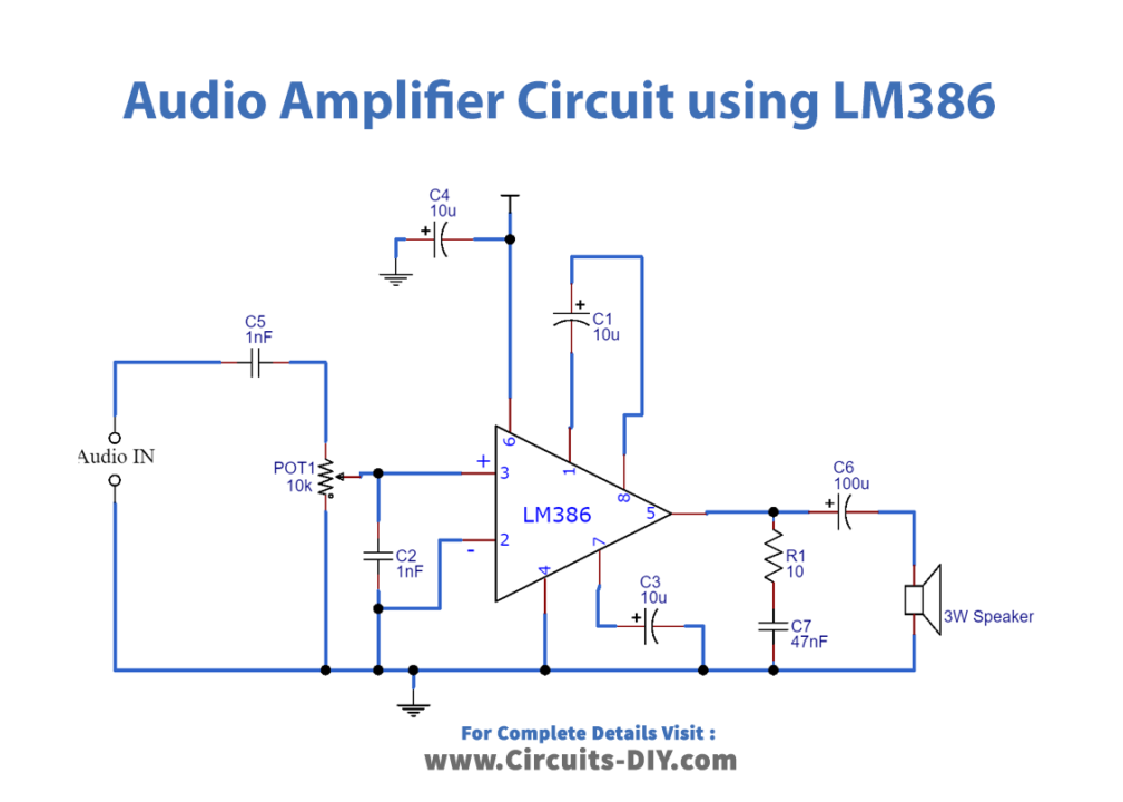
Working Explanation
Connect the power supply to Pins 6 and 4. Connect and audio source using a 3.5mm jack. To control the input voltage level, a variable resistor can be connected to the input. In addition, a capacitor can be connected in series with the resistor to filter out DC components from the input signal. At the output connect a speaker with an impedance in the range of 4Ω to 32Ω. Connect the speaker to Pin 5 through a capacitor to remove DC signals from the output.
The primary operation of LM386 is the gain control provided by Pins 1 and 8. By connecting a capacitor between Pins 1 and 8, the 1.35 KΩ internal resistor is bypassed and the gain is set at 200 (46dB). By adding a resistor in series with the capacitor the gain can be modified pertaining to the requirement. Different values of the resistor will give different gains in the range of 20 to 200.
Apart from gain control the LM 386 can also be used to change the frequency response of the input signal. This can be achieved by connecting a capacitor and resistor in a series between Pins 1 and 5.
The Bypass Pin (Pin 7) provides an output without the gain. Grounding this pin via a capacitor will provide noise reduction and an overall more stable output.
Applications
- AM and FM radios
- Line Drivers
- Ultrasonic Drivers
- Small Servo Drivers
- Power Converters
- Intercoms
- Audio Booster


1 thought on “Simple Audio Amplifier Circuit using LM386”
Comments are closed.