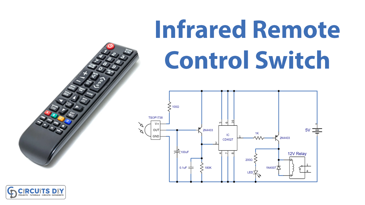
Today we are going to make an interesting project of an Infrared Remote Control Switch. In the early days, remote controls were used to be huge and complex but now with so many technological advances, you can make it yourself easily with a few components.
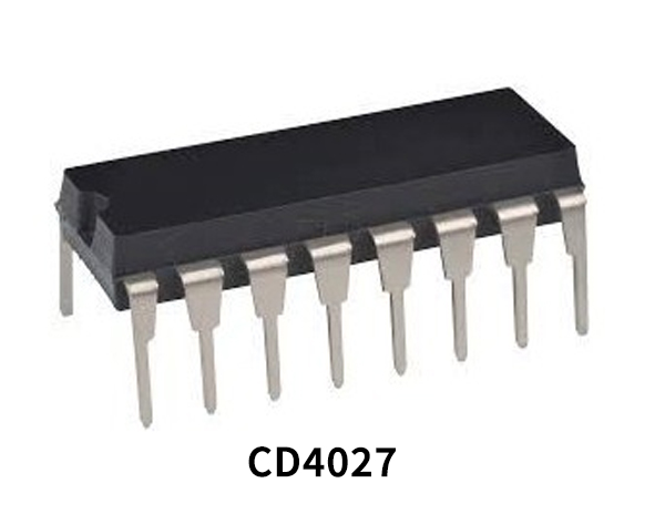
This circuit will connect any appliances like a light, lamp, or fan and you can switch them on and off. The main component of this circuit is an IR sensor TSOP 1738, it is an IR receiver sensor that can receive IR signals of 38KHz. It has a PN photodiode and a preamplifier stage encased in it. The other main component of this circuit is a J-K flip-flop CMOS CD4027 IC which is working as a toggle switch in this circuit.
Hardware Components
| S.no | Component | Value | Qty |
|---|---|---|---|
| 1. | Breadboard | – | 1 |
| 2. | Battery | 5V | 1 |
| 3. | IR sensor | TSOP1738 | 1 |
| 4. | Transistors | 2N4403 | 2 |
| 5. | J-K Flip-flop CMOS IC | CD4027 | 1 |
| 6. | Relay | 5V | 1 |
| 7. | Diode | 1N4007 | 1 |
| 8. | LED | – | 1 |
| 9. | Resistors | 100Ω, 180KΩ, 1KΩ, 200Ω | 1,1,1,1 |
| 10. | Capacitors | 100µF, 0.1µF | 1,1 |
Circuit Diagram
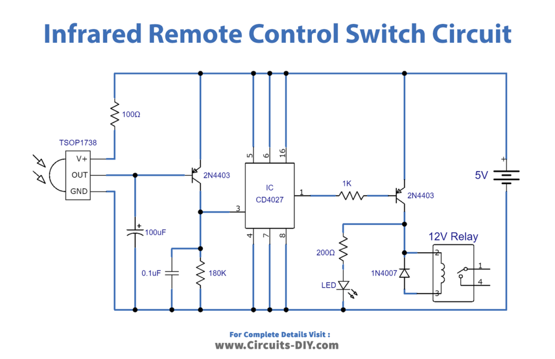
Working
This circuit is operating at 5 volts. The working of this circuit is simple it is using an IR sensor TSOP 1738, flip-flop IC CD4027, two transistors, and a few other discrete components. The IR sensor receives 38KHz IR pulses which are sent to a transistor Q1 for amplification. This amplified signal then goes to the clock 2 pin of the IC. The output of this IC will give voltage to transistor Q2 and it activates. Q2 then activates the 5V relay connected with it. When the relay activates an LED will light up. You can connect any appliance with this relay and it will turn on and off with this circuit.
Applications and Uses
This circuit can be used as a switch for your home appliances such as fans, lights, AC, TV, and CD/DVD Player. You can operate them remotely without leaving your chair