A Mobile Phone charger is a device that charges a mobile phone from an available AC supply source. The Mobile phone chargers available in the market are quite expensive, although, in most of the chargers, the internal circuitry is almost the same as the output pin is different. Which depends upon the type of mobile phone we are using.
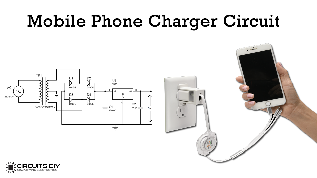
In this tutorial, we will show you how to make a low-cost mobile charger circuit. This circuit will convert 220 Volt AC to regulated 5 Volt DC by using a step-down transformer and some other basic electronic components.
Hardware Required
Following are the necessary hardware items required for Mobile phone Charger Circuit:
| S. No | Components | Value | QTY |
|---|---|---|---|
| 1 | Full-wave bridge rectifier | W04M | 1 |
| 2 | Transformer | 9-0-9 / 1A | 1 |
| 3 | Capacitor | 1000uF, 0.01uF | 1 |
| 4 | Breadboard | – | 1 |
| 5 | Voltage Regulator | LM7805 | 1 |
| 6 | Jumper Wires | – | – |
Connections
- Connect the Full-bridge rectifier to the transformer as shown in the circuit diagram.
- Place the Voltage regulator on the breadboard and connect Pin 1 to 1000uF Capacitor.
- Connect the pin 3 of the voltage regulator to 0.01uF Capacitor and connect Pin 2 to GND.
- At the output, connect a Micro USB pin or use a voltmeter to measure the output voltage.
Working Explanation
Most of the mobile phones generally charge with 5v regulated DC supply, so basically we are going to build a circuit for 5v regulated DC supply from 220V AC. We will use a step-down transformer to convert 220V AC to 9 V AC. The voltage rating of the transformer should always be more than the required output voltage. The 9V AC will then be converted into 9V DC by the full-wave bridge rectifier. You can either use 4 individual diodes for this purpose or use a single full-wave rectifier component.
The output of the full-wave bridge rectifier is not pure DC and has a very high ripple factor. So the 1000uF capacitor will work as a filter capacitor and will remove the ripples from the DC signal. This signal will now be applied to the voltage regulator, which will convert 9V DC to regulated 5V DC. To check the output voltage, connect the voltmeter to the output of the circuit, it should read 5V.
Application
- We can use this circuit as a power source for digital circuits, ICs, microcontrollers, etc.
Mobile Charger Circuit