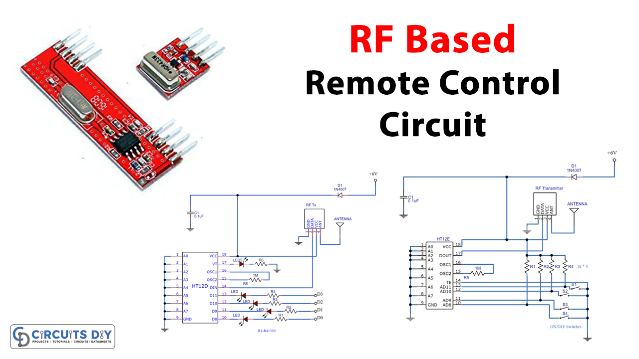
A remote control circuit allows the operation of devices that are out of convenient reach for direct operation of controls. It is an electronic device used to operate another device from a distance, usually wirelessly. They function best when used from a short distance. Here RF remote control circuit is designed with a 434 MHz ASK (Amplitude shift keying) transmitter and receiver. This circuit is constructed by using IC HT12E, IC HT12E, and other easily available components, IC HT12E acts as an encoder, and IC HT12D acts as a decoder, This remote gives approximately 150-meter coverage by extending the ariel wire it can be increased up to 200 meters. This project has two stages which are
- Transmitter circuit
- Receiver circuit
Hardware Required
| S.no | Component | Value | Qty |
|---|---|---|---|
| 1. | Encoder IC | HT12E | 1 |
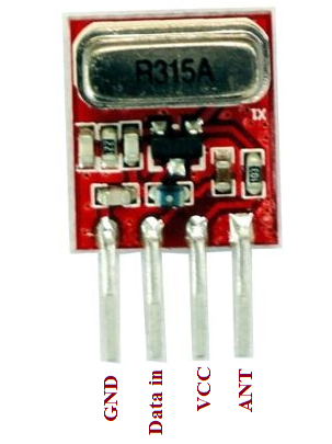
| 2. | RF Transmitter ASK Module | 434 MHz | 1 |
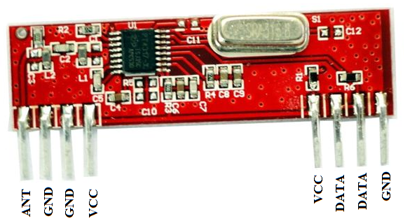
| 3. | RF Receiver ASK Receiver Module | 434 MHz | 1 |
| 4. | Decoder IC | HT12D | 1 |
| 5. | Input Switch | – | 8 |
| 6. | Diode | 1N4007 | 2 |
| 7. | Resistor | 1KΩ,1MΩ,330Ω | 4,2,4 |
| 8. | Capacitor | 0.1uF | 2 |
| 9. | LED | – | 1 |
| 10. | Connecting Wires | – | – |
| 11. | Battery | 6V | 2 |
Transmitter Circuit Diagram
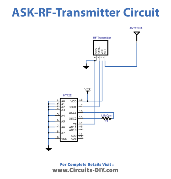
Working Explanation
As we can see in the circuit it includes three stages, first one is an Input switch, the second is an encoder IC HT12E, and then an RF transmitter (434 MHz ASK module). The input switches are connected with encoder ICs data pin, these switches decide the on / off condition by turning on any switch. Here we connect the data input pin of encoder ic to the ground, and the oscillator pins are connected with a 1 MΩ resistor because the encoder ic has an internal oscillator. Address lines A0 to A7 of the encoder are terminated to the ground which is used for address data encoding with a unique identity but we don’t need these pins in this project. Output Dout pin 17 is connected with the data pin of the RF transmitter and the encoded data from IC HT12E is converted as RF signals by the ASK transmitter chip. These signals are transmitted through air, an ordinary wire is enough to transmit an RF signal at a short distance. And by choosing an ariel or antenna we can transmit RF signals to long distances.
Receiver Circuit Diagram
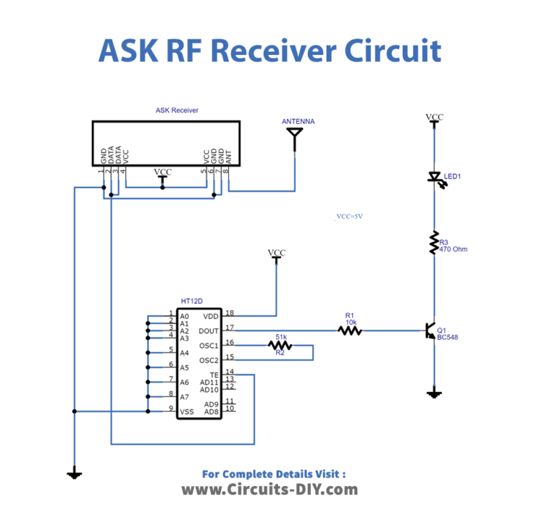
Working Explanation
As we can see, this receiver circuit also has three stages. The first one is the RF receiver (434 MHz ASK receiver module), the second is the decoder IC HT12D, and then the output data line. The RF receiver receives an RF signal that is transmitted by the ASK Transmitter module and gives output through pin 2. Then this signal is fed to input pin 14 of decoder IC HT12D, here the Address pin A0 to A7 are terminated to the ground as done in encoder IC. Hence we ensure the same address in the transmitter and receiver circuit, the decoder IC provides the data output from D3 to D0 pins. As per the switch conditions in the transmitter circuit, these outputs are the same.
ASK Transmitter Module
ASK Receiver Module
Applications
Consumer electronics can be used to operate devices such as a television set, DVD player, or other home appliances.