Simple Time Delay Circuit uses 555 Timer IC to create a time delay. The time delay circuit has 2 switches, one is responsible to start the time delay and the second is responsible to trigger the rest. The circuit also consists of a potentiometer to adjust the time delay. It gives the advantage to vary the time delay.
A 9V battery is used to power the circuit along with the 5V relay which helps in switching the AC load.

Hardware Components
The following components are required to make Time Delay Circuit
| S.No | Component | Value | Qty |
|---|---|---|---|
| 1. | Breadboard | – | 1 |
| 2. | Battery | 9v | 1 |
| 3. | Lamp | 230v | 1 |
| 4. | IC | NE555 Timer | 1 |
| 5. | Electrolytic Capacitor | 2200uF | 1 |
| 6. | Ceramic Capacitor | 0.01uF | 1 |
| 7. | Resistor | 1k, 10k | 4, 1 |
| 8. | Potentiometer | 1M | 1 |
| 9. | Push Buttons | – | 2 |
| 10. | LED | 5mm | 2 |
| 11. | Voltage Regulator IC | LM7805 | 1 |
| 12. | NPN Transistor | BC547 | 1 |
| 13. | Relay | 5v DC | 1 |
555 Pinout
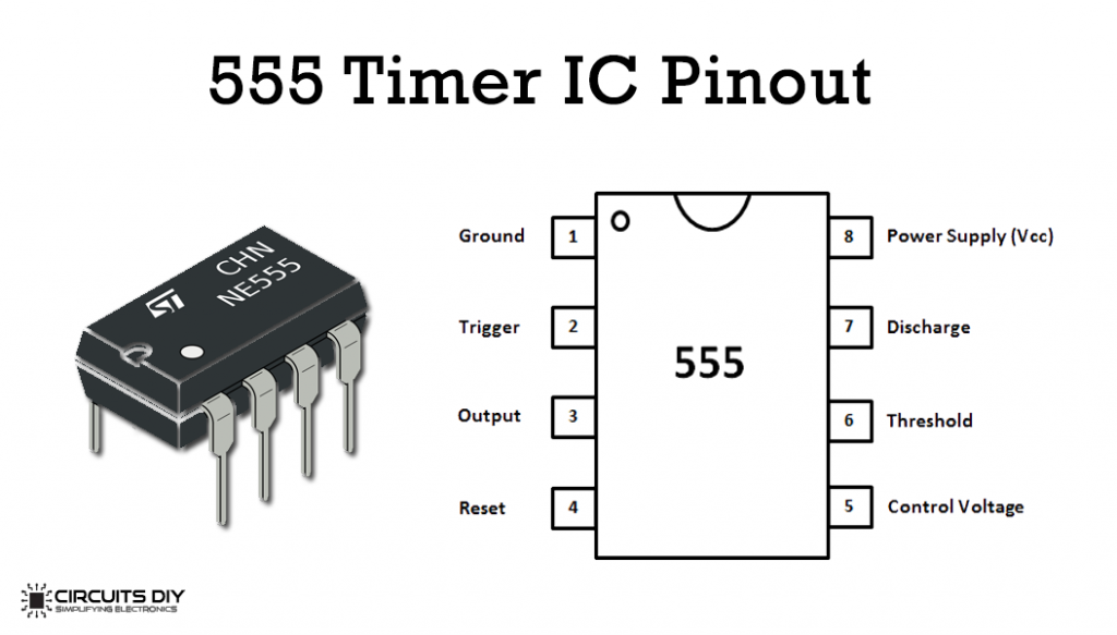
For a detailed description of pinout, dimension features, and specifications download the datasheet of 555 Timer
LM7805 Pinout
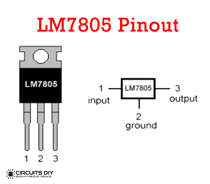
For a detailed description of pinout, dimension features, and specifications download the datasheet of LM7805
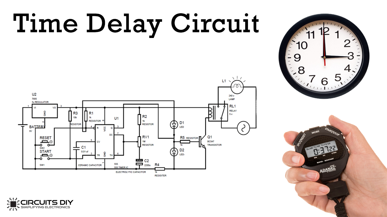
Time Delay Circuit
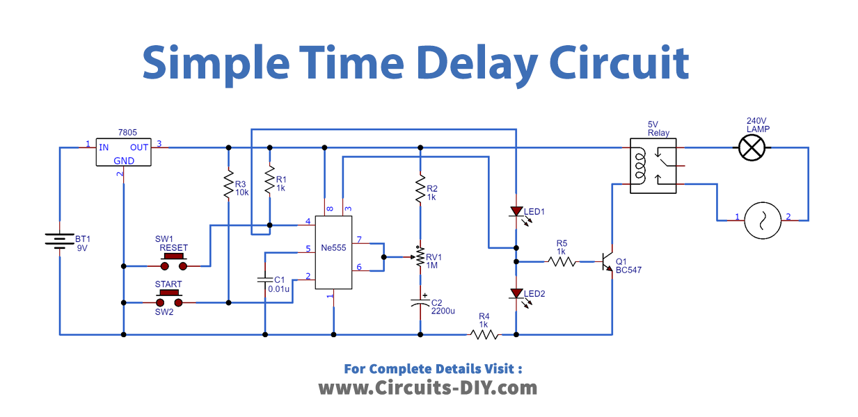
Working of Time Delay Circuit:
The circuit is powered via a voltage regulator. when no button is pressed the output of the 555 timer IC is low and the circuit remains in a low state. Until and unless the start button is pressed and capacitor c1 is in a discharged state.
the time delay for the unstable state depends upon the value of the capacitor and resistor. As the value changes, the time delay for the unstable states also is changed. The Blue LED glows in an unstable state and Red LED glows in a stable state. We can alter the time delay using a potentiometer. We can also connect a Relay to trigger the AC appliance after the time delay.
On pressing the Start button, the countdown timer starts, and Blue LED glows after the particular interval as given by the formula T=1.1*R1*C1, the 555 timer IC goes into the stable state, where the Red LED glows.