Introduction
In developing countries, or also in some developed countries traffic is the major issue. As the automotive industry strengthened, the number of vehicles has also increased and they are now increasing more. However, a lot of vehicles also get jammed in traffic because of not so proper dealing with traffic ideas. Simple Four Way Traffic Light controls the movement of traffic effectively. So we thought why not make this fun project of Four Way Traffic Light Circuit in this article? To make this project with us, you need to scroll down this article a little.
Hardware Required
| S.no | Component | Value | Qty |
|---|---|---|---|
| 1. | IC | NE555 Timer | 1 |
| 2. | Counter IC | CD4017 | 1 |
| 3. | Diode | 1N4007 | 8 |
| 4. | LED | – | 12 |
| 5. | Capacitor | 10μF | 1 |
| 6. | Resistor | 1KΩ, 220Ω | 1, 3 |
| 7. | Potentiometer | 20K | 1 |
| 8. | Battery | 9V | 1 |
| 9. | 2-Pin Connector | – | 1 |
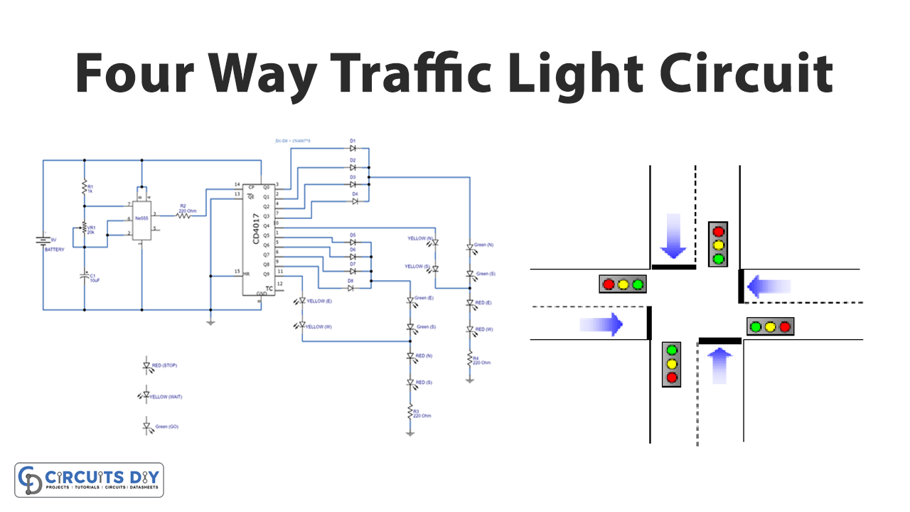
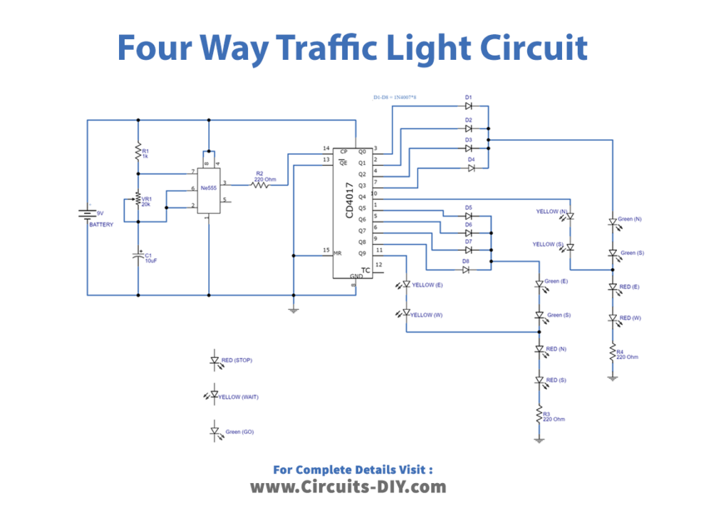
Circuit Diagram
Working Explanation
This Simple Four Way Traffic Light uses the 555 timer IC. The 555 Timer IC works as an astable multivibrator. It creates a pulse wave that relies upon the timing of the resistor and capacitor. We give the pulses into the input of the clock of the counter IC wired in the circuit. This progression the resulting in HIGH or LOW logic. By associating the different colors of LEDs with different signals ( for example, red for stop, green for go, yellow for wait) we can get the result at the output. The circuit is a prototype and can work effectively on large scale, just need a few extra components.
Application and Uses
- In the applications of traffic light systems.
- As a DIY project.