Introduction
When there are so many complicated circuits in electronics that are also difficult to make, there are also some circuits that are fun to make. We always try to come up with different types of circuits, sometimes we try to implement complicated circuits to make them easier for you. While sometimes we try spirited circuits that can break your boredom.
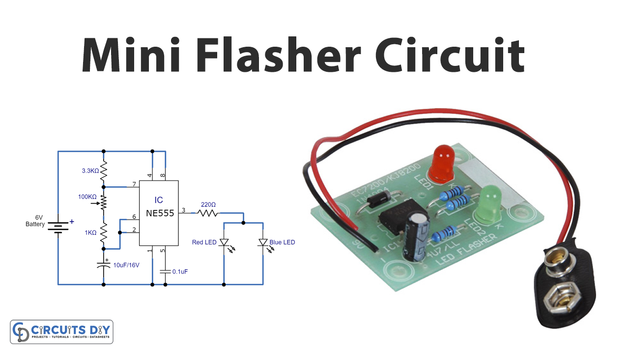
Hence, today in this tutorial, we are going to Make a “Mini Flasher”. If you are a complete beginner, this is one of the easiest circuits to kick start. The circuit uses the LM555 timer IC to generate oscillation and delays.

Hardware Components
The following components are required to make Mini Flasher Circuit
| S.no | Component | Value | Qty |
|---|---|---|---|
| 1. | IC | NE555 Timer | 1 |
| 2. | SMD Potentiometer | 100KΩ | 1 |
| 3. | LED | – | 2 |
| 4. | Capacitor | 0.1µF, 10uF | 1 |
| 5. | Resistor | 220Ω, 3.3KΩ, 1KΩ | 1,1,1 |
| 6. | Connector | 2-Pin | 1 |
NE555 IC Pinout

For a detailed description of pinout, dimension features, and specifications download the datasheet of 555 Timer
Mini Flasher Circuit

Working Explanation
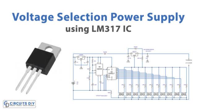
This mini flasher circuit uses the LM555 timer IC, having 8 pins. The power supply is given at pin 8, while pin 1 is for the ground. The capacitor is connected to the control pin 5, which determines the pulse width of the output wave. Pin 4 is the reset pin to apply the Negative pulse to reset the timer IC. Since this circuit it’s not used for reset Purposes, therefore it is connected to VCC pin 8. Thus, it avoids negative triggering. Pin 6 Compares the given voltage to the terminal with the voltage of two-thirds of the VCC. The trigger pin 2 is effective for change of the flip-flop from set to reset. Hence, connected with the threshold pin 6. Output load, that is LEDs are connected at pin 3 of an IC.
Application and Uses
- In signal lights.
- In some display circuits, etc.