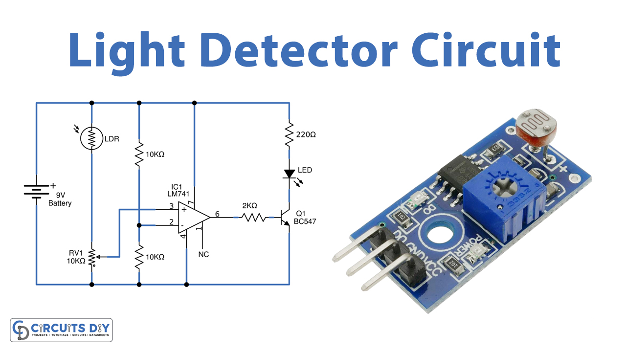
In this tutorial, we are going to make a “Light Detector With Sensitivity Control Circuit”.
The light detector circuit detects the quantity of light present in the environment and the results can be seen by the brightness of the LED. We designed a simple Light Detector With Sensitivity Control Circuit by using LDR (Light Dependent Resistor) and an operational amplifier. There are many photosensors but a very common, inexpensive, and easy-to-use one is LDR. Here LDR acts as a Light detecting sensor and it is placed in a balanced Wheatstone bridge, A 10KΩ Variable Resistor connected with LDR can control the sensitivity of LDR. LDR works effectively even in rough conditions. This light detector circuit is designed to indicate the presence of light through the LED.
Hardware Components
The following components are required to make Light Detector Circuit
| S.no | Component | Value | Qty |
|---|---|---|---|
| 1. | Operational amplifier IC | LM741 | 1 |
| 2. | LDR | 1 | |
| 3. | Transistor | BC547 | 1 |
| 4. | Variable Resistor | 10KΩ | 1 |
| 5. | Resistor | 220Ω, 2KΩ,10KΩ | 1,1,2 |
| 6. | LED | – | 1 |
| 7. | Connecting Wires | – | 1 |
| 8. | Power Supply | 9V | 1 |
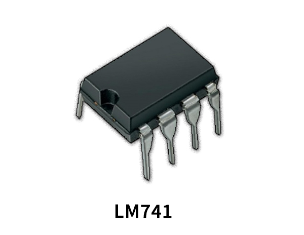
LM741 Pinout
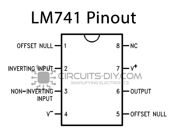
For a detailed description of pinout, dimension features, and specifications download the datasheet of LM741
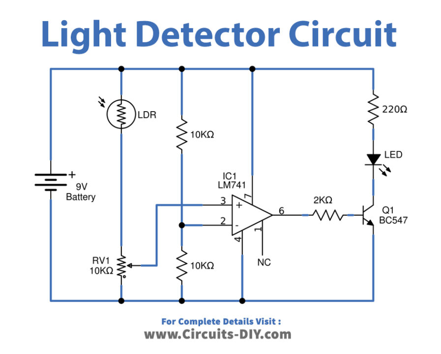
Light Detector Circuit
Working Explanation
As shown in the circuit LDR with variable resistance VR1 forms a voltage divider network. The output of this network is given to non-inverting input. The LDR is a variable resistor whose resistance change according to the intensity of light falling on it. Variable resistor VR1 is used to adjust the sensitivity of LDR i.e., on what intensity of light, the circuit triggers the load (LED). Another input voltage is taken from the voltage divider network using resistor R1 and R2 which forms a voltage divider network that divides Vcc into two parts thus ½ Vcc volt is available at inverting input. Op-amp 741 compares these two voltages and produces output. This output is fed into transistor switch Q1 and the LED glows depending on the Q1 ON and OFF conditions.
If the voltage at pin 3 is high, the output of IC1 is also high and if the volt at pin 3 is low, the output of IC1 is low. The LDR is a variable resistor whose resistance decreases with the increase in light intensity. When light falling on an LDR has low intensity (dependent upon adjustment of variable resistor VR1), its resistor is large enough and the voltage across VR is less than ½ Vref thus the output of IC becomes low. This low output triggers the transistor Q1 and as a result LED starts to glow. However, when light falling on LDR is of large intensity, the resistance of LDR falls and the voltage drop across VR1 is large enough (more than ½ Vcc). Thus, the output of IC becomes high. This high output drives the transistor in an off state and as a result LED goes OFF.
Applications
It can be used to control the (switch on and off) electrical load appliances like lights, fans, coolers, air conditioners, street lights, etc., automatically.