Multiple led flasher circuit is a circuit with patterns of Light flashing from the LED. The circuit includes just the timer IC NE555 and a combination of resistors and capacitors.

Hardware Components
The following components are required to make LED Flasher Circuit
| S.no | Component | Value | Qty |
|---|---|---|---|
| 1. | LED | – | 6 |
| 2. | Battery | 12V | 1 |
| 3. | Variable resistor | 100KΩ | 3 |
| 4. | Resistor | 75Ω, 10KΩ | 1,3 |
| 5. | Electrolytic capacitor | 10µF | 3 |
| 6. | IC | NE555 Timer | 1 |
555 IC Pinout

For a detailed description of pinout, dimension features, and specifications download the datasheet of 555 Timer
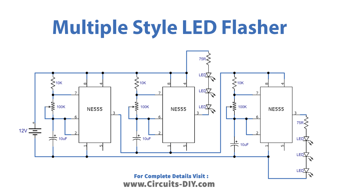
LED Flasher Circuit
Working Explanation
All three ICs in the circuit are working in their Astable Multivibrator form. In this case, the IC generates rectangular pulses of set time duration. The IC1 is directly connected to the battery supply and is responsible to power IC2 and IC3. The two ICs, IC2, and IC3 have three LEDs connected at their output. Furthermore, the time duration of the two ICs differs so that the blinking time of LEDs are differently achieved. For this purpose, a 100KΩ variable resistor sets the time duration of the rectangular pulse.
The operating voltage of the circuit is 12V but it works well between a 6V-15V battery supply. However, say, for operating the circuit at 9V, use two LEDs in place of the three for both the ICs as well as a suitable current limiting resistor. For an increase in the blinking pattern if you are to add more LEDs, then connect an NPN transistor at the output of IC2 and IC3. Moreover, a relay of voltage rating same as that of the battery supply can also be connected at the output of the two ICs to light up a 220V bulb.
Application
- Parties lighting decoration
- home lighting system