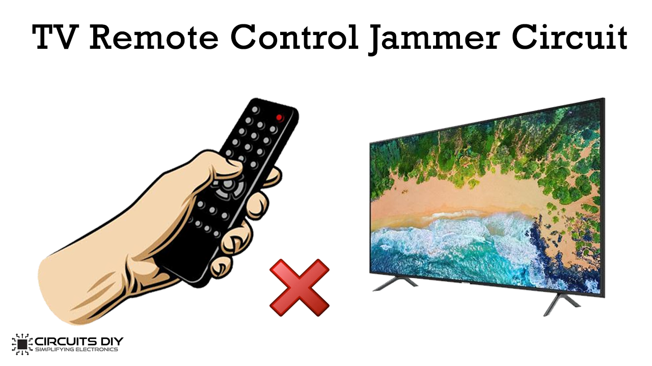
In this project, we are going to design a TV remote jammer circuit. This is a very simple circuit and an interesting concept. The circuit stops the working of the TV remote. Basically, it blocks the communication established between the TV and the remote control.
The communication between the TV and remote control is IR (Infrared) communication. This circuit confuses the IR receiver on the TV by producing a constant signal. This interferes with the remote control signal. Once you switch on the circuit the TV will not be able to receive any signal from the remote. So basically this circuit is an IR jammer circuit.

Hardware Components
The following components are required to make the Remote Control Jammer Circuit
| S.No | Component | Value | Qty |
|---|---|---|---|
| 1. | Breadboard | – | 1 |
| 2. | IC | NE555 Timer | 1 |
| 3. | IR LED | – | 2 |
| 4. | Resistors | 220 ohm, 1k, 10k | 1, 1, 1 |
| 5. | NPN Transistor | 2N2222 | 1 |
| 6. | Potentiometer | 100K ohm | 1 |
| 7. | Capacitor | 10nF or 22nF | 1 |
| 8. | Battery | 9v | 1 |
| 9. | Connecting Wires | – | 1 |
555 IC Pinout

For a detailed description of pinout, dimension features, and specifications download the datasheet of 555 Timer
Remote Control Jammer Circuit
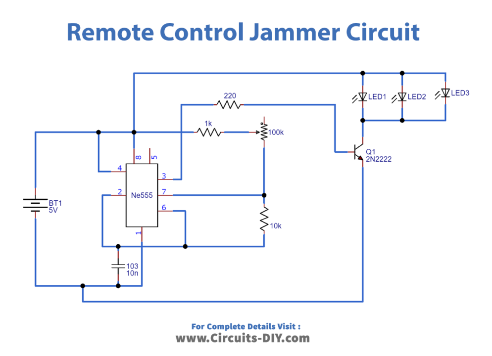
Working Explanation
The fundamental technology which the TV remote uses is Infrared Light. This IR light is invisible to the human eye but can be seen through the camera. The TV remote generates a pattern of pulses whenever a button is pressed. The IR transmitter is present in the TV remote. It generates the pulses for every button in a different and unique way. The IR receiver is present on the TV end. It receives the unique sequence of pulses and identifies which button is pressed. The important fact behind the TV remote control jammer circuit is sending a constant IR pulse with the carrier frequency of the transmitter. As a result, no signal will be accepted by the receiver. Hence no action will be taken.