Introduction:
A tachometer is an instrument or a device that is designed to measure the rotations of any rotating object. It is basically used to measure the speed of a shaft or a disk in a machine or a motor. The measuring unit of the device is rotation per minute. It is just like a speedometer that measures the revolutions per minute of any vehicle. It has a dial and a needle to indicate the readings, on contact with the surface of the rotating object. The meter has safe and dangerous markings to indicate the limits.
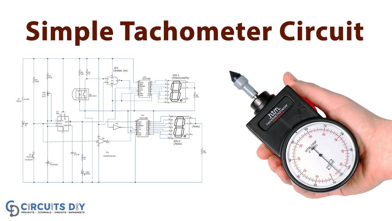
We can build a simple tachometer circuit at home using easily available components which can be used for detecting the rotations of any rotating object. Since the circuit contains two seven segments it can display the values from 00 to 99 RPS count, you can add more segment displays for larger values.
Hardware Components
The following components are required to make Tachometer Circuit
| S.no | Component | Value | Qty |
|---|---|---|---|
| 1. | Seven-segment display | LTS 543 | 2 |
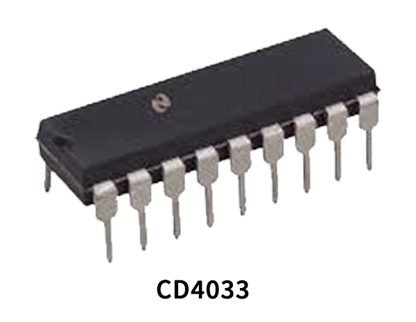
| 2. | Decade counter IC | CD4033, CD4081, CD4069 | 2, 1, 2 |
| 3. | IC | NE555 timer | 1 |
| 4. | MOC IC | 7811 | 1 |
| 5. | Capacitor | 100µF, 0.01µF | 1 |
| 6. | Battery | 9V | 1 |
| 7. | Resistor | 470Ω,1KΩ, 220KΩ, 8.2KΩ, 220Ω | 2, 2, 1, 1, 1 |
| 8. | AND logic gate | – | 1 |
| 9. | Variable Resistor | 4.7KΩ | 1 |
| 10. | Switch | – | 1 |
| 11. | Push-button | – | 1 |
CD4033 Pinout
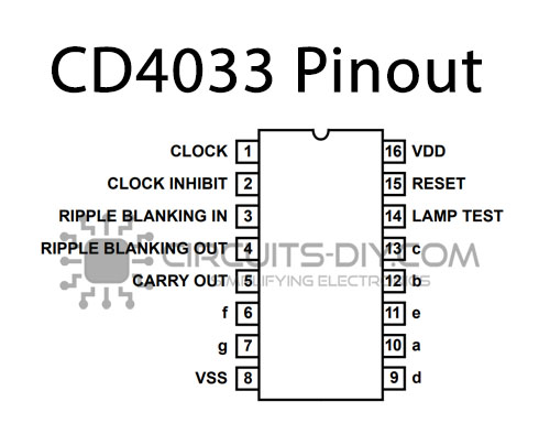
For a detailed description of pinout, dimension features, and specifications download the datasheet of CD4033
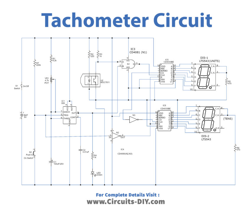
Tachometer Circuit
Construction:
The circuit uses a 555 timer IC as IC1, MOC IC 7811 as IC2, IC CD4081 as IC3, IC CD4069 as IC4, and two CD4033 IC as IC5 and IC6, and two common-cathode seven-segment displays (each LTS543) along with some passive components.
The DIS1 is connected to the output of decade counter IC5 to display the unit place value while the DIS2 is connected to the output of decade counter IC6 to display the tens place value. As the count overflows that it reaches digit 9 (maximum digit), the IC5 generates a pulse which acts as a clock input to the IC6 through a NOT gates N3. It means when the count of the unit’s place reached 9, there will be the first increment in the tens place.
Working Explanation:
The IC 555 is configured in a monostable multivibrator mode to generate a clock pulse when the switch S2 triggers the IC, the time period of the IC is set by the variable resistor VR1. The output pin3 is coupled with the pin2 of AND gate N1. The IC2 senses the rotating of the motor, as the shaft rotates it cuts the internal beam of light and hence the pulses are generated by IC2. These pulses act as an input source for AND gate N1. The RPS of the shaft is measured by pressing the S2 shortly, the switch triggers the timer IC which enables the AND gate N1 for the time duration of one second. The IC receives the pulses as a clock input and for each clock pulse, the counter increments its value to drive the seven segments.
Applications & Uses:
The tachometer as mentioned is a device used to measure the rotation of any object and hence is used vastly in many instruments and devices.
- Many motor vehicles, airplanes, trains, etc. use a tachometer.
- The laser instruments or devices also use a tachometer.
- It is used in industrial motors and pumps to measure vibrations.
- The device used to determine the rate of blood flow also uses a tachometer.
- Hence, a tachometer has many industrial, commercial, and personal uses.