In this project, we are making a timer with an alarm circuit. This circuit is simple and is using a CD4060 IC. CD4060 is a CMOS 14 stages binary counter IC that is used for timing applications, it has ten active high outputs. It gives a time delay from a few seconds to hours. This IC needs a only few components and you can easily construct a simple and reliable time delay circuit. The other IC used in this circuit is a 555 timer IC, it is the most versatile IC used for electronic circuits. It is used to provide time delays or oscillations to the circuit.
In our project, the circuit is adjustable to provide a timing cycle ranging from 1 minute to many hours.
Hardware Components
The following components are required to make Timer Circuit
| S.no | Component | Value | Qty |
|---|---|---|---|
| 1. | Input Supply DC | 9-12V | 1 |
| 2. | IC | CD4060 | 1 |
| 3. | IC | NE555 Timer | 1 |
| 4. | Transistor | 2N3904 | 1 |
| 5. | Speaker | – | 1 |
| 6. | Resistor | 2.2MΩ,16KΩ,1MΩ,5.6KΩ,15KΩ,1.2KΩ | 1, 1, 1, 1, 1, 1 |
| 7. | Variable Resistor | 1MΩ, 1KΩ | 1, 1 |
| 8. | Ceramic Capacitor | 470nF, 0.01µF | 1 |
| 9. | Electrolytic Capacitor | 100µF, 10µF | 1 |
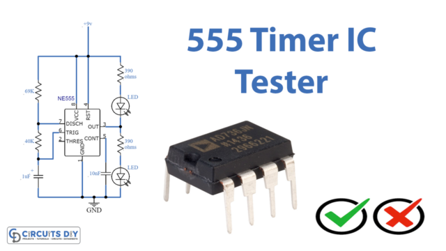
NE555 IC Pinout

For a detailed description of pinout, dimension features, and specifications download the datasheet of 555 Timer
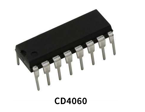
CD4060 Pinout

For a detailed description of pinout, dimension features, and specifications download the datasheet of CD4060
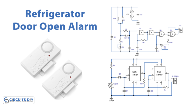
Timer Circuit
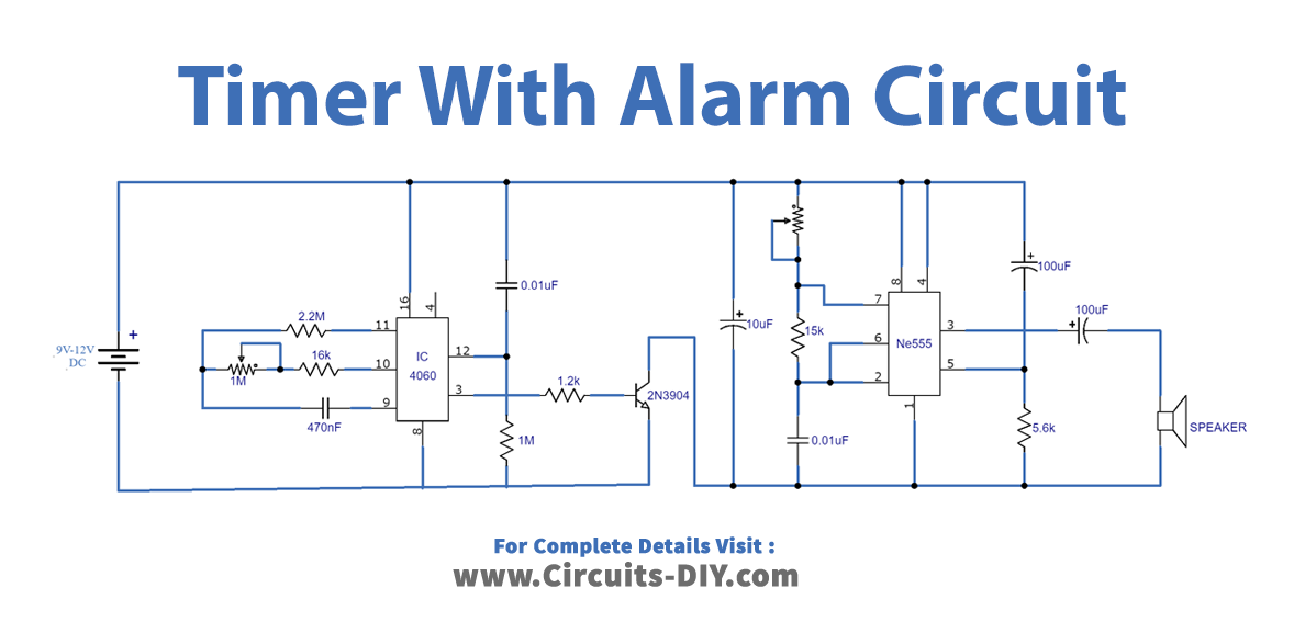
Working Explanation
The operating voltage of this circuit is 9 to 12 volts DC. The circuit is divided into two parts, the first part is built around the CD4060 CMOS IC. This IC has a built-in oscillator that is stable and has a wide range of frequencies. The oscillator frequency can be adjusted by the components connected to pins 9, 10, and 11. The other part of this circuit is an alarm circuit built around 555 IC. The sound intensity of this alarm can be adjusted with the help of a variable resistor, here we have used 1K.
The standby current consumption of this IC is low. The timing cycle can be adjusted with the help of the 1M ohms variable resistor or it can also be determined by changing the values of the components at pins # 9,10 and 11.