Introduction
Keep your food fresh and your energy bills low with a Refrigerator Door Open Alarm Circuit! This simple circuit alerts you every time the refrigerator door is left open, helping you avoid unnecessary energy waste. Whether you’re forgetful, have kids who love to snack, or want to save some money, this circuit is the solution you need. With just a few components and a little know-how, you’ll be able to build your very own door-open alarm in no time. So, grab your tools, and let’s get started!
Hardware Required
You will require the following hardware for Refrigerator Door Open Alarm Circuit.
Figure 1 Table Circuit
| Components | Value | QTY |
| IC | IC1, IC2 2 Timer 555 | 1, 1 |
| Polar Capacitor | C1: 1uf 25V | 1 |
| Non Polar Capacitor | C2: 100nF | 1 |
| Resistor | R1: 10K 1 / 4W, R2: LDR (photoresistor), R3: 2.2M 1 / 4W, R4: 1M 1 / 4W | 3 |
| Diode | D1:1N4148 | 1 |
| Buzzer | Piezo type DC | 1 |

Figure 2 Circuit Table
| S.no | Components | Value | QTY |
|---|---|---|---|
| 1 | IC | 4093(N1,…N4) | 1 |
| 2 | Polar Capacitor | 10uF | 2 |
| 3 | Non Polar Capacitor | 470, 10nF | 1, 1 |
| 4 | Resistor | 10k, 1M, 1k | 1, 2, 1 |
| 5 | Variable Resistor | 25k, 10k | 1, 1 |
| 6 | LDR | – | 1 |
| 7 | Buzzer | – | 1 |
| 8 | Switch | – | 1 |
| 9 | Battery | 9V | 1 |

Working Explanation
You can see two circuits in the above heading of the circuit diagram. Let’s explore them individually.
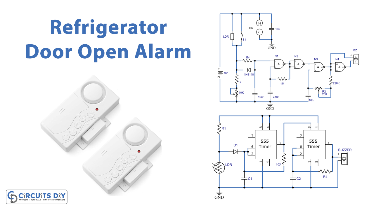
Circuit 1 (Figure 1)
The circuit uses a photosensor LDR to detect whether the door is open or not. If the door is open and the light inside the fridge falls on the LDR, the circuit produces an alarm. The circuit is powered by a PP3 9-volt battery and should be placed as close to the light inside the fridge as possible.
The circuit consists of two timer ICs 555. When the LDR is not exposed to light, the voltage on pin 2 of the first IC 555 remains high, and its output (pin 3) is low. This inhibits the second IC 555 and prevents the alarm from turning on. When the door is open, and the LDR is exposed to light, the voltage on pin 2 of the first 555 drops. This causes its output to oscillate and activate the second 555, which starts oscillating at a higher frequency. This, in turn, activates the buzzer, which starts buzzing and alarming.
Circuit 2 (Figure 2)
This fridge door security alarm is designed to alert you if the fridge door has not been correctly closed by sounding an alarm. The circuit uses an LDR (light-dependent resistor) or a microswitch to detect. When the door is opened, the fridge light illuminates the LDR, or the microswitch is pressed, the circuit is activated, and a warning sound is triggered until the door is closed again. The circuit uses timer ICs and a piezo buzzer to produce the alarm sound.
We can adjust the volume and sensitivity of the alarm with preset P1 and P2, respectively. The circuit is designed to be used with a 9V battery and can be housed in a waterproof box. The circuit uses approximately 0.5 mA in an idle condition and 4 mA when the alarm sounds.
Final Words
In conclusion, making a refrigerator door open alarm circuit is a simple and effective way to ensure that you always remember to close the fridge door again. Following the step-by-step instructions, you can easily build this circuit. Ask away any questions, and we’ll try to respond. Happy building!