Introduction
Low-voltage alarm circuits are essential to maintaining electrical systems’ safety and efficiency. These circuits are designed to detect and respond to low voltage levels, alerting technicians and operators to potential issues before they can cause damage or disruption. This can prevent costly downtime and protect equipment from damage due to low voltage conditions.
Beyond safety, low-voltage alarm circuits are also valuable in helping to conserve energy. By detecting low voltage levels and shutting down non-essential equipment, these circuits can help to reduce overall energy consumption and costs. Additionally, low-voltage alarm circuits can be used to monitor and manage the power supply of remote or off-grid systems, ensuring that they have the necessary voltage to operate correctly.
So, let’s dive into this tutorial to make the low-voltage alarm circuit!
Hardware Required
You will require the following hardware for Low Voltage Alarm Circuit.
| S.no | Component | Value | QTY |
|---|---|---|---|
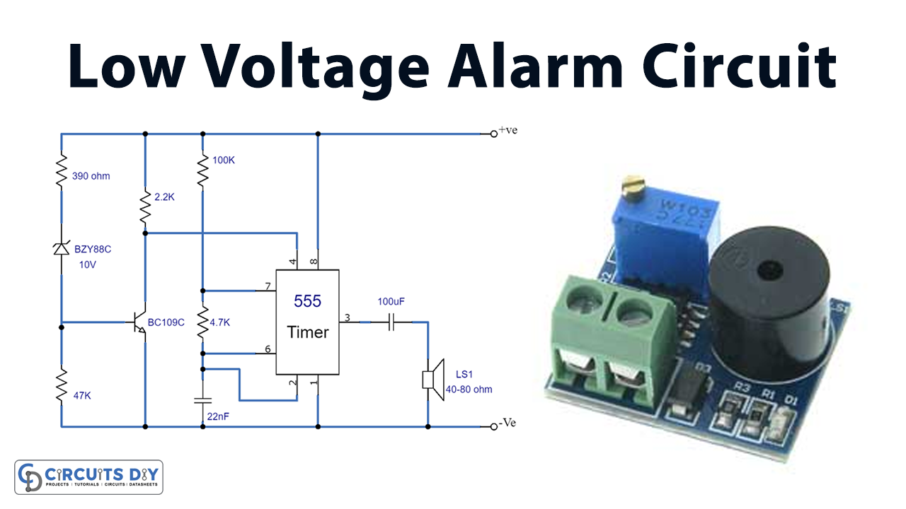
| 1. | IC | NE555 Timer | 1 |
| 2. | Capacitor | 22nF, 100uF | 1, 1 |
| 3. | Resistor | 390, 2.2, 4.7, 100k | 1, 2, 1, 1 |
| 4. | Transistor | BC109C | 1 |
| 5. | Diode-10W | BZY88C | 1 |
| 6. | Speaker | 40-80 OHM | 1 |
| 7. | Jumper Wire | – | 1 |
Circuit Diagram

- The alarm can be built with a toggle switch to activate or deactivate it. The threshold voltage of this circuit may be changed on demand. For this, D1’s operating Voltage must be adjusted.
- D1 has a voltage differential of 0.5 volts compared to a Zener diode. The latter may also serve as a suitable substitute for D1. However, there is a maximum threshold voltage that the circuit can withstand.
- The 555 gadget can handle voltages up to 16 volts. In other words, it shouldn’t be utilized in places where high voltages might cause harm.
- The circuit can have a voltage error of 0.5 volts, but this is acceptable.
Working Explanation
The low-voltage alarm circuit is designed to alert you when the voltage of a 12-volt battery drops below a certain level. The circuit consists of a 555 astable integrated circuit that generates a loudspeaker alarm signal. The astable requires a certain amount of voltage to function, which is supplied to pin 4 of the 555 IC.
The circuit also includes a diode (D1) and a transistor (Tr1), which work together to control the voltage flow to the astable. When the voltage supplied to the diode is above a certain level (10.5 volts or its avalanche voltage), the diode becomes “biased” and allows current to flow through it. This helps to ensure that there is enough voltage across resistor R2 for the transistor to function correctly.
The diode stops conducting when the voltage drops below 10.5 volts, and the transistor cuts off. This causes the voltage across resistor R3 to charge up, which in turn charges up pin 4 of the 555 IC. Once the voltage at pin 4 is high enough, the astable starts working again, and the alarm signal is sounded.
The circuit is designed to be energy-efficient, consuming only 10mA of power, which is a small amount compared to the capacity of a typical 12-volt car battery. This means that the circuit will not drain the battery quickly and can be used for a long time before needing to be replaced. Overall, this circuit is a simple and effective way to alert you when your car battery’s voltage drops below a critical level, helping you avoid being stranded with a dead battery.
Final Words
To sum up, constructing a Low Voltage Alarm Circuit is a creative and satisfying activity. It takes a few simple tools and a small bit of expertise for anybody to build this circuit. Feel free to post any questions or issues you may have here, and we will do our best to answer them.