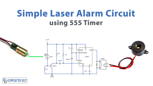
Introduction
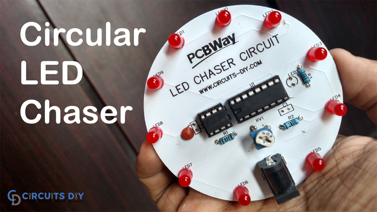
Are you bored with making typical projects that give you a lot of stress and tension? Let us help you by providing this tutorial where we will make the dancing LED circuits. It’s actually an LED chaser circuit using 555 timer IC and counters IC CD4017 as its major components. The CD4017 IC is a 10-output,16-pin CMOS decade counter. So, The. Whenever a clock signal from the clock input is delivered, it has ten decoded outputs that give output signals one by one in sequence.
The CD4017 IC is one of the most cost-effective ICs for counting applications. It’s essentially an IC with ten decoded outputs and the ability to count from 0 to 10. With ten output pins, the CD4017 is a CMOS decade divider or counter. As a result, this IC is used in a variety of industries, including medical, electronics, and the automobile industry. The finest part is that it occupies relatively little space in circuits or devices, making it more appealing to users. In addition, the IC is available in the electronic market at relatively low prices.
PCBWay commits to meeting the needs of its customers from different industries in terms of quality, delivery, cost-effectiveness, and any other demanding requests. As one of the most experienced PCB manufacturers in China. They pride themselves to be your best business partners as well as good friends in every aspect of your PCB needs.
Hardware Components
The following components are required to make LED Chaser Circuit
| S.no | Component | Value | Qty |
|---|---|---|---|
| 1. | Decade Counter IC | CD4017 | 1 |
| 2. | PCB board for circuit | – | 1 |
| 3. | IC | NE555 Timer | 1 |
| 4. | Potentiometer | – | 1 |
| 5. | power jack | – | 1 |
| 6. | Capacitors | 1uF, 0.01uF | 1, 1 |
| 7. | Resistors | 10K, 680 ohms | 1, 2 |
| 8. | Battery | 9V | 1 |
| 9. | LEDs | – | 11 |
CD4017 Pinout
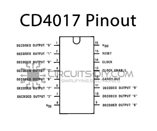
For a detailed description of pinout, dimension features, and specifications download the datasheet of CD4017
NE555 IC Pinout

For a detailed description of pinout, dimension features, and specifications download the datasheet of NE555 IC
LED Chaser Circuit

Working Explanation
In this LED Chaser Circuit using 555 and 4017, the clock input of the CD4017 decade counter IC is wired to the NE555 timer. The timer IC provides the decade counter’s CLK input with square wave input. Each pin on the CD4017 connects to an LED. By default, the ic’s output pin is high while it turned the remaining pins off. When the clock input pin of the 4017 IC detects a voltage rise from low to high, it turned the current output off and the next consecutive output is gets turned on.
This output change, which appears to be the LEDs chasing each other, continues until it reached the last LED, at which point the output is reset to the first LED.
Applications and Uses
- For decoration purposes.
- Display systems.
- Integrated electronic circuits, etc.