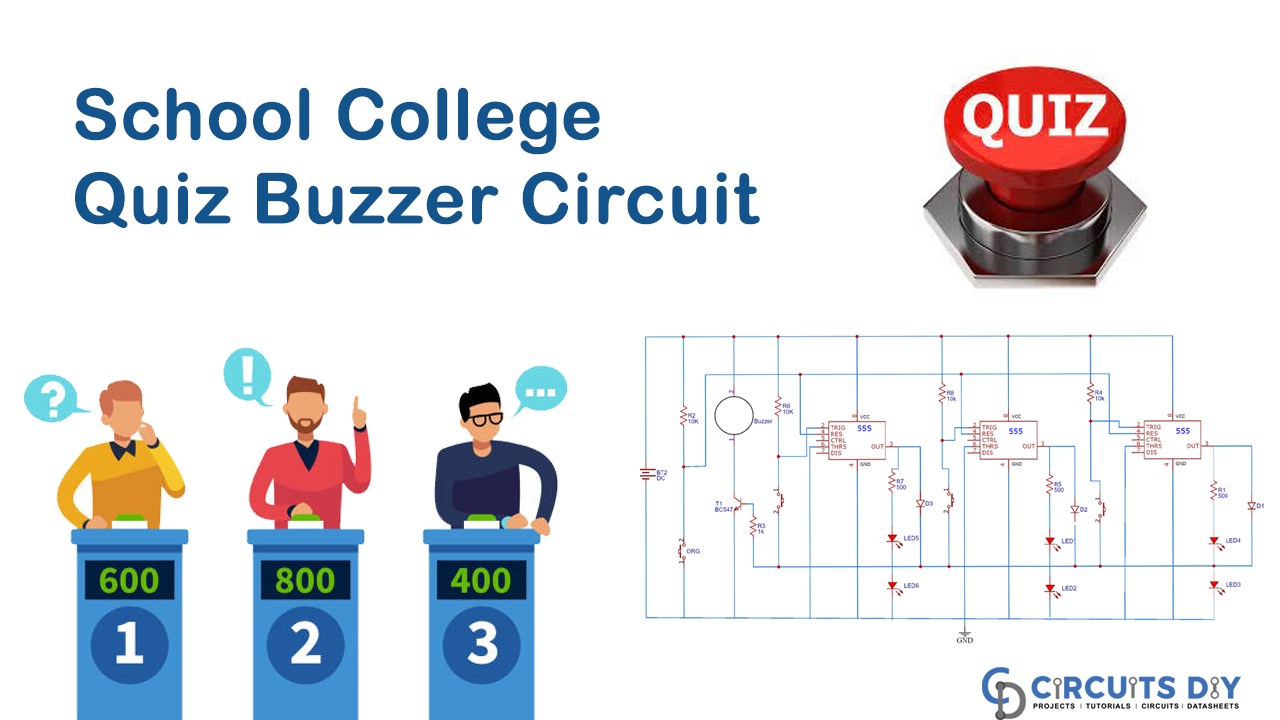
In this DIY, we are demonstrating the School/College Quiz Buzzer Circuit using 555 Timer IC which is easy to make and requires a few components. “Quiz” is a significant occasion because it is used to test the information and knowledge in schools or colleges when any student knows the answer, he or she pushes the buzzer and indicates that he or she knows the answer first.
So, it will be hard for the teacher who organizes the competition who push the buzzer first, so there is a feature in our quiz buzzer circuit that if anyone pushes the buzzer first, then other buzzers will become disabled.

Hardware Component
The following components are required to make Quiz Buzzer Circuit
| S.no | Component | Value | Qty |
|---|---|---|---|
| 1. | Diode | 1N4007 | 3 |
| 2. | IC | NE555 timer | 3 |
| 3. | Tactile switch | – | 4 |
| 4. | Transistor | BC547 | 1 |
| 5. | Buzzer | – | 1 |
| 6. | Breadboard | – | 1 |
| 7. | Connecting wires | – | – |
| 8. | Resistor | 1KὨ, 10KὨ | 7, 4 |
NE555 IC Pinout

For a detailed description of pinout, dimension features, and specifications download the datasheet of 555 Timer
Quiz Buzzer Circuit
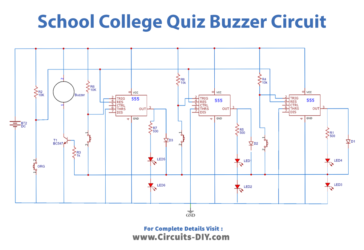
Working Explanation
In this section, we will discuss the working of the “School/College Quiz Buzzer Circuit.” In this circuit, we have used three 555 timer ICs. The significant part is each 555 IC will have its own steady-state constrained by isolated buttons which will be given to the students. Another single button controls the other stable condition of all the 555 timer ICs in a like manner, which is given to the coordinator to reset the whole circuit.
When any of the buttons P1, P2, or P3 is pressed, the relating TRIGGER pin gets low, and the “timer” moves its steady-state, and the yield pin of the “timer” goes high. Furthermore, the Green LED corresponding to the students turns on, and the “buzzer” begins signaling.
Applications and Uses
This Quiz Buzzer Circuit is used in schools/colleges or any event for quiz competition between the participants.