Introduction
In electronics, timers are the circuits that provide the signal that changes the state of the system. To understand this, in this tutorial, we are going to “Adjustable Timer Circuit using 555”. And, to make this circuit we are using the widely used timer IC NE555. The 555 timer IC is one of the most used ICs in the electronic circuits world. It’s an integrated circuit that has so many applications in timer, delays, oscillator, and pulse generator. The integrated circuit contains 8 pins having different definitions. The favorable element of this circuit is that it’s reasonable in price and credible like any other op-amp.
Pin Configuration of 555 timer IC
- Pin 1: Connects to the ground
- Pin 2: Trigger pin. It needs one-third of the supply voltage for triggering. It has a high impedance and can work with 1uf.
- Pin 3: Output Pin
- Pin 4: To reset the circuit. The voltage should be 0.8 or less to reset.
- Pin 5: Control pin
- Pin 6: Threshold pin. Have high impedance and can work with 0.2uA.
- Pin 7: Discharge
- Pin 8: Power supply
Hardware Required
| S.no | Component | Value | Qty |
|---|---|---|---|
| 1. | IC | NE555 Timer | 1 |
| 2. | Buzzer | 9V | 1 |
| 3. | Potentiometer | 1M | 1 |
| 4. | Capacitor | 1000μF/16V | 1 |
| 5. | Resistors | 10KΩ, 10Ω/1W | 1, 1 |
| 6. | Battery | 9V | 1 |
| 7. | 2-Pin Connector | – | 1 |
| 8. | Push Button Switch | – | 1 |
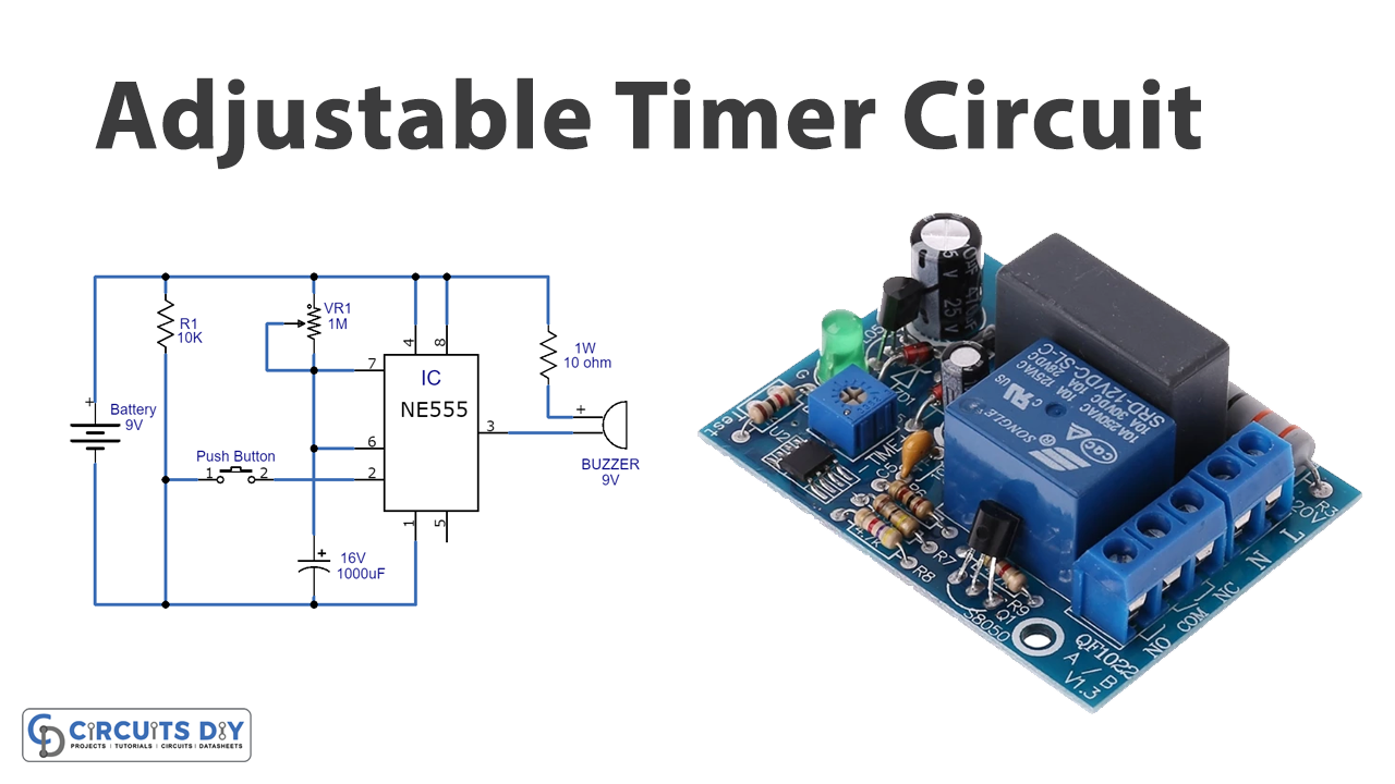
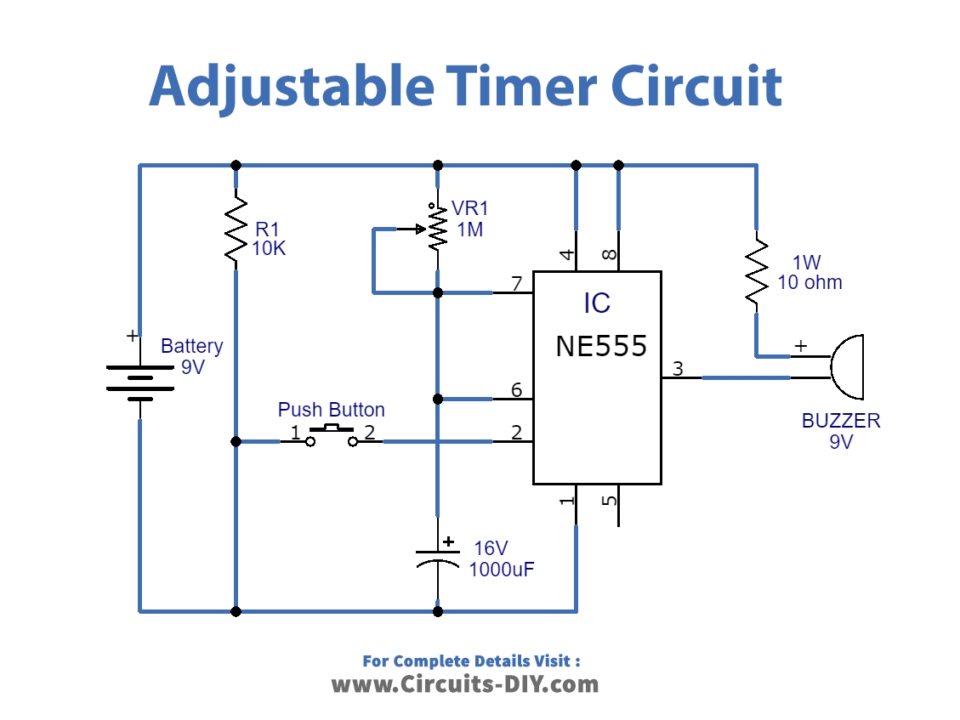
Circuit Diagram
Working Explanation
To build this Adjustable Timer Circuit using 555, the IC is working as a monostable multivibrator. And, for this, connect trigger pin 2 to the ground supply with the help of the push-button switch. When you press the push-button, trigger pin 2 gets the negative supply and therefore triggers the 555 timer IC. IC starts its operation. Potentiometer VR1 and capacitor C1 are working as the timing components, connected across the power supply. The discharge pin and threshold pin are connected and then get wired to the timer elements. We connect the output to the 9V using a 10-ohm Resistor. Vcc and reset pins are connected with the positive terminal of the 9V battery. While pin 1 is connected with the ground of the 9V battery.
Application and Uses
- Duty cycle oscillators.
- Flip Flops.
- Pulse width modulation circuits, etc.