Once Tom Lehrer said; “Life is like a Piano, what you get out of it depends on how you play it.” It is an integral part of music, and music lovers can’t ignore its melodious sound. But, when it comes to purchasing, it is pretty much expensive. Therefore, today we have come up with a simple and basic tutorial for a DIY Piano with few electronic components.
Here, the DIY Piano is fabricated by associating a 555 timer variable frequency ASTABLE multivibrator to a speaker. Undeniably, the piano is a brilliant musical instrument and one can make a modest one utilizing a 555 timer IC chip.
This idea of the piano is accomplished by causing the timer IC to create 5-15 diverse sorts of sounds. However, the various sounds are produced through timer IC by permitting it to run as a free-running mode or astable mode, or square wave mode, with a variable frequency yield alternative.
Hardware Components
The following components are required to make Electronic Piano Circuit
| S.no | Component | Value | Qty |
|---|---|---|---|
| 1. | Supply voltage | 9-12 V | 1 |
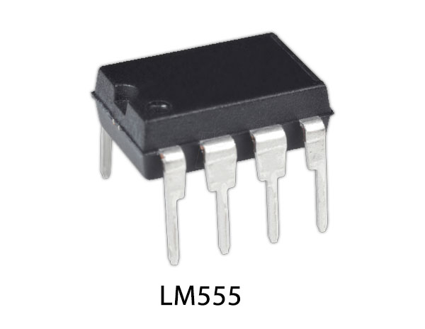
| 2. | IC | LM555 timer | 1 |
| 3. | Resistor | 2.2K, 10K, 100R | 1, 5, 1 |
| 4. | Variable Resistor | 100K | 1 |
| 5. | Electrolytic Capacitor | 10µF, 100µF | 1, 1 |
| 6. | Speaker | 8Ω, 0.5W | 1 |
| 7. | Button | – | 6 |
NE555 IC Pinout

For a detailed description of pinout, dimension features, and specifications download the datasheet of 555 Timer
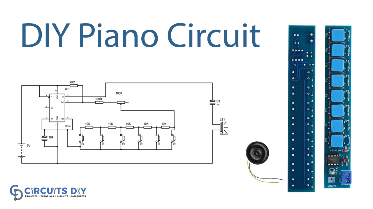
Electronic Piano Circuit
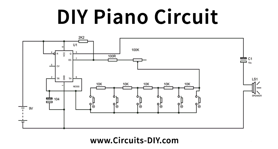
Working Explanation
The above circuit diagram shows the circuit connection of the piano or ASTABLE with various frequencies. In this circuit think about a case, if a push-button from the left is squeezed, then the resistance somewhere in the range of pin7 and pin6 goes as (i.e. 100k + Potentiometer resistance). For instance, consider the frequency created here is a 1KHz square wave thus we get a tone. Henceforth, if the second button from the left is squeezed, the resistance somewhere in the range of pin7 and pin6 goes as (i.e. 100k + Potentiometer resistance + 10K resistance).
Thus at this resistance value, here the frequency of the square wave created is not the same as that of the initial one as the successful opposition has changed somewhere in the range of pin7 and 6. With this frequency change of square wave, we get an alternate tone to the first. This is the way every push button is set up in the circuit to create a new frequency tone.
Applications and Uses
- Use to play music