In this tutorial, we are going to make a very useful project of a Repeating timer using two 555 timer ICs. Timer circuits are used to provide time delays of a particular interval for switching a connected load. This circuit is different than other timer delay circuits because it is providing a continuous-time cycle on pushing the button S1.
There are two outputs in this circuit that are used to activate any device of your choice. You can connect two separate relay switches with these two outputs to operate two different AC/DC devices.

Hardware Components
The following components are required to make a Repeating Timer Circuit
| S.no | Components | Value | Qty |
|---|---|---|---|
| 1. | Battery | 9-12V | 1 |
| 2. | Switch | – | 1 |
| 3 | IC | NE555 Timer | 2 |
| 4. | LED | – | 2 |
| 5. | Resistor | 10K, 470Ω | 2, 2 |
| 6. | Variable resistor | 1MΩ | 2 |
| 7. | Electrolytic Capacitor | 220µF | 2 |
| 8. | Ceramic Capacitor | 0.1µF, 1000pF | 2, 1 |
| 9. | Connecting Wires | – | 1 |
| 10. | Breadboard | – | 1 |
NE555 IC Pinout

For a detailed description of pinout, dimension features, and specifications download the datasheet of 555 Timer
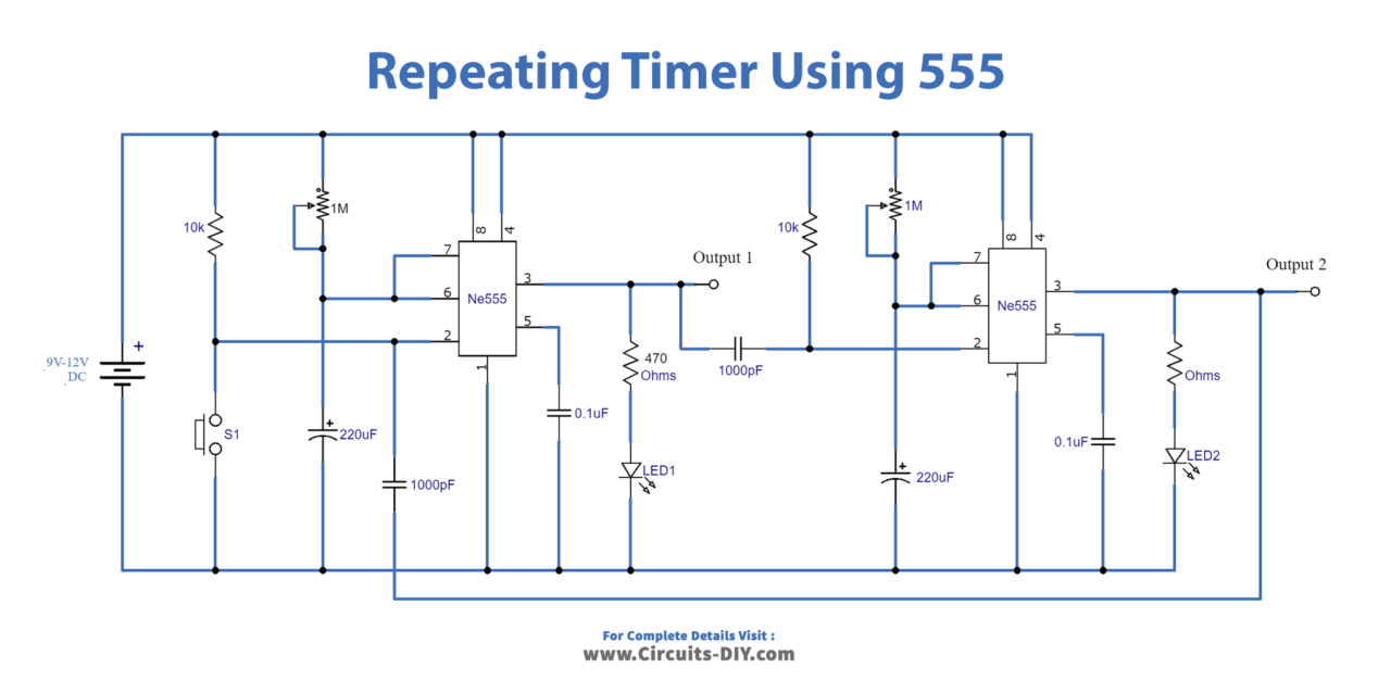
Repeating Timer Circuit
Working Explanation
The operating voltage of this circuit is 9-12V. Both 555 timer ICs are working in time delay mode. A variable resistor of 1M is used with both ICs to adjust their duration of time delay. This time delay can also be adjusted by the capacitor. Here we have used 220uF, you can increase the value of the capacitor to increase the timing.
On pressing the push button S1, IC1 will be triggered and its output becomes high. When the time period of IC1 is over it will deactivate and activates the IC2. When the time period of IC2 gets over its output will become low which will again trigger the IC1. This process will keep repeating itself providing two outputs simultaneously. LEDs are used at the output of both ICs along with a current limiting resistor for the visual indication of their outputs.