Introduction
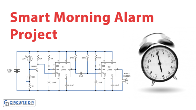
Astable Multivibrators are oscillators that continuously oscillate between two states, providing two square wave output waveforms. “The fast running or self trigger mode” is another term for astable multivibrator mode. However, unlike a mono-state multivibrator, it does not have a stable state. A stable multivibrator, on the other hand, has two quasi-stable states: state high and state low. In addition, in the astable multivibrator, there is no external triggering. The high and low states are determined by the time length of both resistors and capacitors. In a nutshell, this multivibrator is astable when oscillating at a certain frequency and rectangular wave pulse. So, in this tutorial, we are going to make an “Astable Multivibrator”
Certainly, multivibrators that are mostly astable exist to induce time delays in circuits. It also includes connecting resistors and capacitors, as well as the 555 timer IC. The output time is modulated by resistors and capacitors. To get the ON and OFF timings, choose the right resistors and capacitors.
Hardware Required
| S.no | Component | Value | Qty |
|---|---|---|---|
| 1. | IC | NE555 Timer | 1 |
| 2. | Variable Resistor | 100KΩ | 1 |
| 3. | Capacitor | 0.01uF, 10uF | 1,1 |
| 4. | Resistor | 330Ω | 1 |
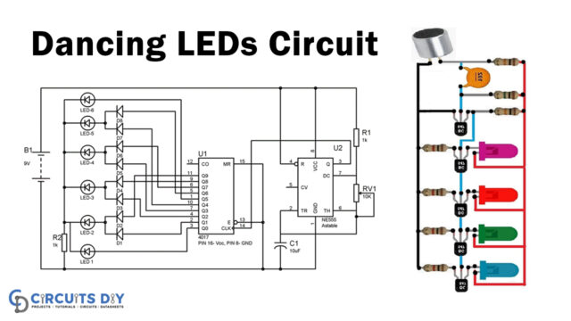
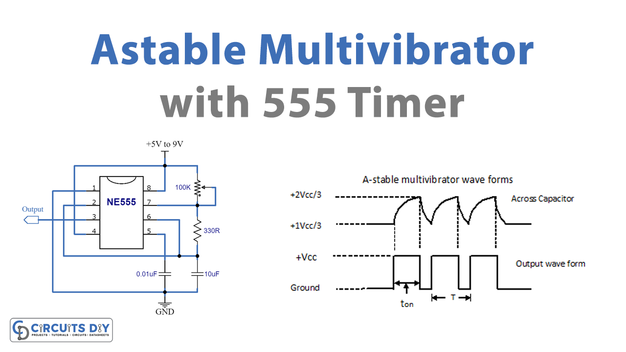
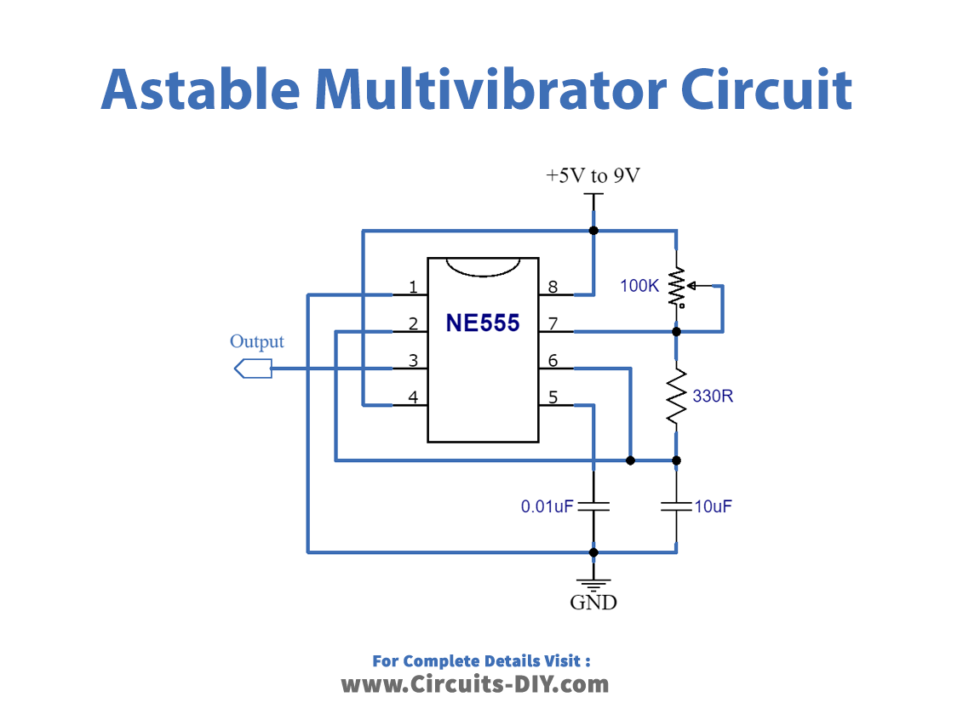
Circuit Diagram
Working Explanation
With the addition of three external components, the IC 555 may be turned into an astable multivibrator. There is no requirement for an external trigger pulse because pins 2 and 6 are linked. It will self-trigger and operate as a multivibrator that runs on its own (oscillator). The following are the remaining connections: we attached the supply voltage to pin 8. Because Pin 3 is the output terminal, the output is available here. The external reset pin is pin 4. The timer will be reset if this pin is briefly low. As a result, pin 4 is normally connected to VCC when not in use. The control voltage changes the threshold voltage level applied at pin 5. We wired Pin 5 to ground through a capacitor in regular operation, filtering off extraneous noise from the terminal. The ground terminal is pin 1.
Application and Uses
- pulse position modulator.
- Frequency Modulators.
- To generate pulses required for different circuits.