In this tutorial, we are going to make a very useful project of a Battery Full Charge Alarm circuit. This circuit indicates a buzzer sound when the battery is fully charged. It can be used with all kinds of batteries of different voltages.
There are a lot of automatic battery chargers available on the market. They will stop your battery from getting charged once it is full but they lack the ability of audio indication. With this audio indication, user can attach their next battery for charging which saves time and electricity.

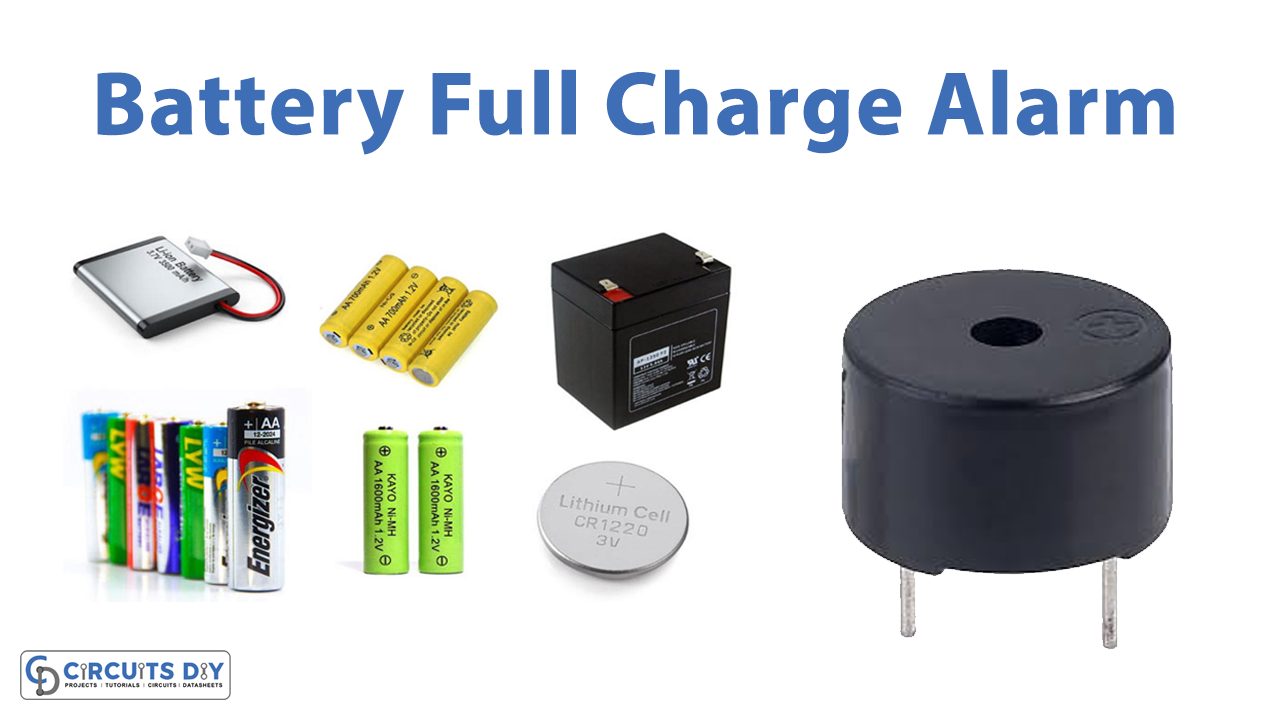
Hardware Components
The following components are required to make Battery Charge Alarm Circuit
| S.no | Component | Value | Quantity |
|---|---|---|---|
| 1. | IC | NE555 Timer | 1 |
| 2. | Op-amp IC | LM358A | 1 |
| 3. | Zener Diode | 6.2V | 1 |
| 4. | LED | – | 1 |
| 5. | Buzzer | – | 1 |
| 6. | Resistor | 10K, 1K, 470Ω | 1, 1, 1 |
| 7. | Electrolytic Capacitor | 10µF | 1 |
| 8. | Ceramic Capacitor | 0.1uF | 1 |
| 9. | Potentiometer | 10K, 100K | 1, 1 |
NE555 IC Pinout

For a detailed description of pinout, dimension features, and specifications download the datasheet of 555 Timer
LM358A Pinout

For a detailed description of pinout, dimension features, and specifications download the datasheet of LM358A
Battery Charge Alarm Circuit

Working Explanation
The working of this circuit is simple. We are using two ICs in this circuit. The first IC is LM358A which is an operational amplifier. The other IC is a 555-timer IC. The battery undercharging is placed in this circuit. A preset 10K resistor along with a 6.2V Zener diode is used at the input of the op-amp IC.
When the battery is fully charged the op-amp receives the signal and produces an output. This output signal becomes the input of the 555 timer IC. We have used a combination of resistors, variable resistors, and a capacitor to adjust the time duration of the output of this 555 timer IC. When it receives the signal it provides an output that activates the LED and the buzzer for the preset time duration. In this way, the user will know that the battery is charged fully so they can reinstall the battery where it was removed from or charge another battery instead.
Circuit Adjustments:
Before using this circuit you need to do some adjustments first.
- Do not attach the battery to the circuit, use a variable power supply first.
- Set the voltage of the variable supply exactly the same as the voltage of your battery.
- Adjust the variable resistor of the op-amp until the LED turns on. That will be the preset value for your battery.
- Now the adjustments are done, you can connect your battery under charge with this circuit and use it.
Applications and Uses
This circuit can be used for batteries of different kinds. It can also be used with solar chargers. You will get an indication of when the battery is fully charged by solar panels. It will help you save the wasted energy of the solar panels.