
The Panic Alarm allows a person under duress to quickly call for help in the event of an emergency. There are many types of panic alarm circuits available. Some have a single pushbutton and others have two pushbuttons to turn on and turn off the alarm. In this tutorial, I will show you how to make a PanicAlarm circuit with two push buttons. At the output, I have connected an LED and a buzzer which can be turned on and off by using the SET or RESET pushbutton.

Hardware Components
The following components are required to make Panic Alarm Circuit
| S. NO | Component | Value | Qty |
|---|---|---|---|
| 1. | Breadboard | – | 1 |
| 2. | Battery | 9v | 1 |
| 3. | Ceramic Capacitor | 0.01uF | 1 |
| 4. | IC | NE555 Timer | 1 |
| 5. | NPN Transistor | BC547 | 1 |
| 6. | Push Button | – | 2 |
| 7. | LED | 5mm | 1 |
| 8. | Buzzer | – | 1 |
| 9. | Resistors | 10k ,1k | 2, 2 |
555 IC Pinout

For a detailed description of pinout, dimension features, and specifications download the datasheet of 555 Timer
Circuit Diagram
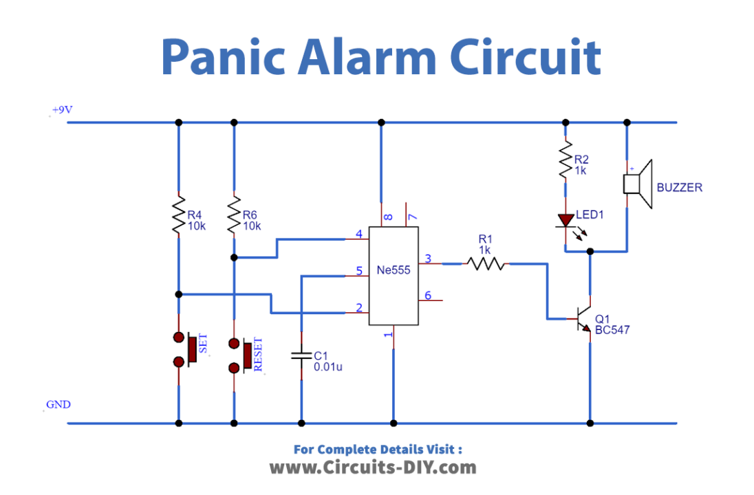
Connection
- Place the 555 Timer IC and Push switches on the breadboard.
- Connect 10K Resistors from VCC to Pushbuttons.
- Use jumper wires to connect Pushbuttons to GND.
- Connect Pin 1 to GND and Pin 8 to VCC.
- Connect Pin 2 to Pushbutton (SET) and connect Pin 4 to Pushbutton (RESET).
- Use a jumper wire to connect the emitter of the transistor to GND.
- Add a Buzzer between the Collector of the transistor and the VCC.
- Add an LED using a 1K Resistor between the Collector of the transistor and the VCC.
- Use a 1K Resistor to connect Pin 3 to the base of the transistor.
Working Explanation
In this circuit, we are operating 555 Timer IC in Bistable mode. This means that the circuit will have two stable states and we can switch between the two states by using pushbuttons. We will use the SET pushbutton to turn on the alarm and the RESET pushbutton to turn off the alarm. The output Pin 3 of the 555 timers is connected to the base of the transistor and it controls the current flow from the collector terminal to the emitter. The buzzer and LED are connected to the collector of the transistor because the current of the 555 timers is not enough to drive both of them, so we will amplify the current by using a transistor.
Application
- This circuit can be used to alert third-party monitoring services in case of an emergency event.
- You can replace the switch with any sensor if you want the alarm to turn on automatically in an event of an emergency.