Introduction
In different electrical circuits and mechanical machines, the motors play out a persuasive job. Servo motors are routinely a device that is used in every other machine and we profoundly utilized them in automation, and mechanical applications. In addition, these motors are likewise having an essential influence on robots and consequently took on advanced mechanics applications. However, these motors cannot work without their critical component which is the driver circuit, the major control of these motors. For this explanation, there are various kinds of drivers which are accessible in the electronic market. However, in this article, we will make that circuit by ourselves. So, In this tutorial, we are going to make a “Servo Motor Driver Circuit”
Hardware Required
| S.no | Component | Value | Qty |
|---|---|---|---|
| 1. | IC | NE555 Timer | 1 |
| 2. | NPN Transistor | BC547 | 1 |
| 3. | Switch | – | 2 |
| 4. | Ceramic Capacitor | 10nF, 100nF | 1, 1 |
| 5. | Resistor | 10KΩ, 36KΩ, 68KΩ 220Ω | 2, 1, 1, 1 |
| 6. | Battery | 9V | 1 |
| 7. | 3-Pin, 2-Pin Connector | – | 1, 1 |
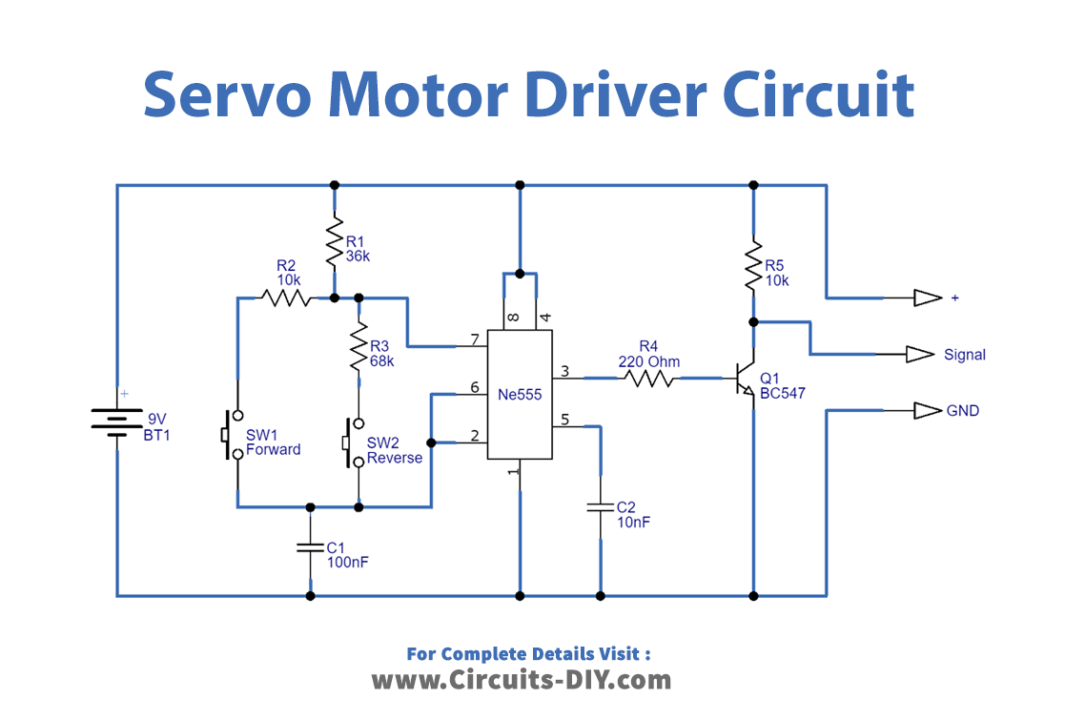
Circuit Diagram
Working Explanation
In this Servo Motor Driver Circuit, we use IC 555 as an astable multivibrator and it generates the pulses at the output with two diverse duration. The pulse time of the output of 555 timer IC depends on the timing resistor and Capacitor wired in the circuit.
When the switch SW1 is closed, the 555 clock IC generates a long duration pulse, and the servo rotates in the clockwise direction And, when the switch SW2 gets closed, the 555 clock IC produces a short duration high pulse and the servomotor rotates antilock wise. Thus, this is how the circuit works.
Application and Uses
- You can use this in different automation circuits.
- In robotics, like robotic arms, or grippers.
- In elevator circuits, etc