In this circuit, we are making a Low Battery Cutoff For 12V Batteries Using 555 IC. The rechargeable batteries are expensive and whenever they get fully discharged they lose some percent of their capacity. Because of this, the battery’s life becomes short. This circuit will solve this issue. It will cut the battery from the load and save it from complete discharge when the voltage of the battery will fall below 12V.

Hardware Components
The following components are required to make Low Battery Cutoff Circuit
| S.no | Component | Value | Quantity |
|---|---|---|---|
| 1. | Battery | 12V | 1 |
| 2. | IC | NE555 Timer | 1 |
| 3. | Phototransistor | PC817 | 1 |
| 4. | Transistor | 2N4403 | 1 |
| 5. | Relay | 12V | 1 |
| 6. | Diode | 1N4007 | 1 |
| 7. | Zener diode | 5.6V | 1 |
| 8. | Resistor | 24K, 470R, 8.2K, 10K, 1K | 1, 1, 1, 1, 1 |
| 9. | Variable Resistor | 10K | |
| 10. | Ceramic Capacitor | 10nF | 1 |
| 11. | Electrolytic Capacitor | 22uF | |
| 12. | LED | – | 1 |
NE555 IC Pinout

For a detailed description of pinout, dimension features, and specifications download the datasheet of 555 Timer
2N4403 Pinout
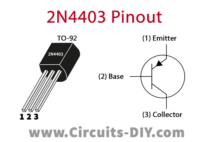
For a detailed description of pinout, dimension features, and specifications download the datasheet of 2N4403
Low Battery Cutoff Circuit
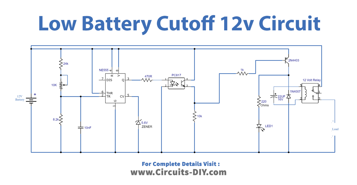
Working Explanation
This circuit is using a 555 timer IC which is wired as an astable multivibrator. A 10K variable resistor is used to adjust the desired voltage at which you want to cut the battery from the load. The LED is used for the indication, it goes off when the battery gets full and the load gets cut off.
The relay used in this circuit should be according to your load otherwise it won’t work. You can use any type of battery with this circuit like SLA, NiCd, Lead-acid, NiMH, etc.
Circuit Adjustment
After you are done building this circuit it requires some calibration first. In order to do that you will need a variable power supply and set its voltage to 11.9V and connect it to the place of the battery in the circuit.
- Adjust the variable resistor until the LED turns off.
- By increasing the voltage of the power supply to 13.5V, check if the circuit is exactly calibrated to cut the load on 11.9V.
- Now again bring the voltage to 11.9V slowly and see if the LED & the relay goes off on 11.9V.
- After these calibrations disconnect the variable power supply from the circuit and connect your desired battery of 12 volts. Now your circuit is ready to use.
Applications and uses
This circuit can be used with any project in which a 12V battery is used such as solar plants, UPS, etc.