This article will cover a list of top-tier simple beginner projects that we have covered on this platform. These projects will cater to all of your beginner needs, but we wouldn’t recommend you to choose these projects as your Final year projects. This list contains a combination of our tested DIY projects, which are tailored especially for beginners to electronics. So let’s jump right in and take a look at the Top 10 Simple Electronics Projects For Beginners. offered by experts from assignment help service CWAssignments.
While selecting the projects for this article out of many others, we have taken care to serve you with the most popular circuits on our website that are very easy to implement. So, the following are our Top 10 Simple Electronics Projects
1) Simple USB Lamp
A USB Lamp circuit is an electronic circuit that serves the function of providing emergency light fixtures. It is a relatively cheap and affordable circuit. You can easily build this project with a minimum number of components.
Hardware Components
You will need the following parts to build this project.
| S.No | Component | Value | Qty |
|---|---|---|---|
| 1. | USB Plug | Type ‘A’ (male) | 1 |
| 2. | Resistor | 47 Ohm | 1 |
| 3. | LED | 5mm, white | 1 |
| 4. | Breadboard | – | 1 |
| 5. | Connecting Wires | – | As per need |
Circuit Diagram

Circuit Operation
The 47 ohms resistor limits the current to 25mA and it is ideal for operating a bright white LED. You can easily connect this circuit to any extra or scrap USB cable you have.
It’s intended mode of operation is through a laptop in case of a sudden power outage.
2) Water Level Indicator
On No. 2 of our Top 10 Simple Electronics Projects is a simple water level indicator project. Water level indicators are simple electronic circuits used to identify the current level of any liquid under observation. They are an important part of various processes such as cooling tower early warning systems, irrigation control, fuel tank level gauging & sump pumps.
Hardware Components
You will need the following parts to build this project
| S.No | Component | Value | Qty |
|---|---|---|---|
| 1) | PNP Transistors | A1015 | 3 |
| 2) | PVC Tubing | – | As per need |
| 3) | Probes (Aluminium/ Copper Wires) | – | 3 |
| 4) | LEDs | 5mm (Red, Green. Blue) | 3 |
| 5) | Resistors | 470Ω | 3 |
| 6) | Battery | 9V | 1 |
| 7) | Battery Clips | – | 1 |
| 8) | Breadboard | – | 1 |
| 9) | Connecting wires | – | As per need |
Circuit Diagram

Circuit Operation
Whenever the tank gets full, we get alerts on particular levels. Here we have created 3 levels (low, medium and full) with respect to the tank capacity. We have added 3 LEDs to indicate the three levels (Low, Medium, Full).
The base of each transistor joins to an aluminum or copper wire with end insulation removed, acting as a probe. When water is rising the base of each transistor gets an electrical connection to 9V DC through water and the corresponding probe. This, in turn, makes the transistors conduct to glow LED and indicate the level of water.
3) Laser Tripwire Alarm
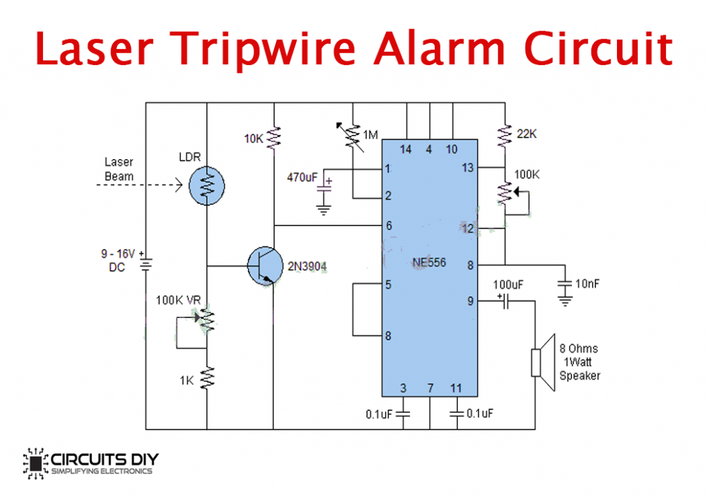
At No. 3 in our list of Top 10 Simple Electronics Projects ranks Laser tripwire alarm project is a very useful security feature that one can employ in his/her home to keep out burglars and intruders. It can detect the movement of people or objects while they are passing through the laser beam and provide trigger alarms as alert signals to proper authorities.
Hardware Components
You will need the following parts to build this project
| S.No | Component | Value | Qty |
|---|---|---|---|
| 1) | Timer IC | NE556 | 1 |
| 2) | Laser Diode Circuit (input) | – | 1 |
| 3) | Loudspeaker | 8Ω, 0.5W | 1 |
| 4) | LDR | – | 1 |
| 5) | NPN Transistor | 2N3904 | 1 |
| 6) | Potentiometer | 1MΩ, 100K | 2 |
| 7) | Resistors | 22KΩ, 10KΩ, 1KΩ | 3 |
| 8) | Capacitors | 470μF, 0.1μF, 100μF, 10μF | 4 |
| 9) | Battery | 9V DC | 1 |
| 10) | Battery Clips | – | 1 |
| 11) | Breadboard | – | 1 |
| 12) | Connecting Wires | – | 1 |
Circuit Diagram
Circuit Operation
When any object comes in between the laser beam and the LDR, the timer section of the circuit will become activated for a preset time period and will subsequently switch ON the buzzer circuit built around the NE556 timer IC. The preset time period can be increase or decrease by changing the value of the 470μF capacitor. The time period for the timer section can be adjusted with the 1MΩ pot.
4) Beeper Circuit
A Beeper circuit is a simple electronic device that produces a monotonous beeping sound, that can be used to signal an emergency situation in places such as hospitals, police stations or Fire brigade stations. Typical uses of beepers include devices such as alarm devices, timers, etc.
Hardware Components
You will need the following parts to build this project
| S.No | Component | Value | Qty |
|---|---|---|---|
| 1) | 2-Input NAND gate IC | CD4011 | 1 |
| 2) | NPN Transistor | 2N4401 | 1 |
| 3) | Piezoelectric Buzzer | 3V | 1 |
| 4) | LED | 5mm | 1 |
| 5) | Electrolytic Capacitor | 470μF | 1 |
| 6) | Resistors | 1KΩ, 1.2KΩ, 470Ω | 3 |
| 7) | Battery | 9V | 1 |
| 8) | Battery Clips | – | 1 |
| 9) | Breadboard | – | 1 |
| 10) | Connecting Wires | – | 1 |
Circuit Diagram

Circuit Operation
Here, the 2 NAND gates are wired as an astable multivibrator due to which the output at pin4 of the IC continuously goes high and low. This continuously toggles the 2N4401 transistor (ON & OFF) which provides the drive for the piezoelectric buzzer. Hence, the piezo-buzzer generates beeps and the LED flashes continuously.
5) Metal Detector Circuit
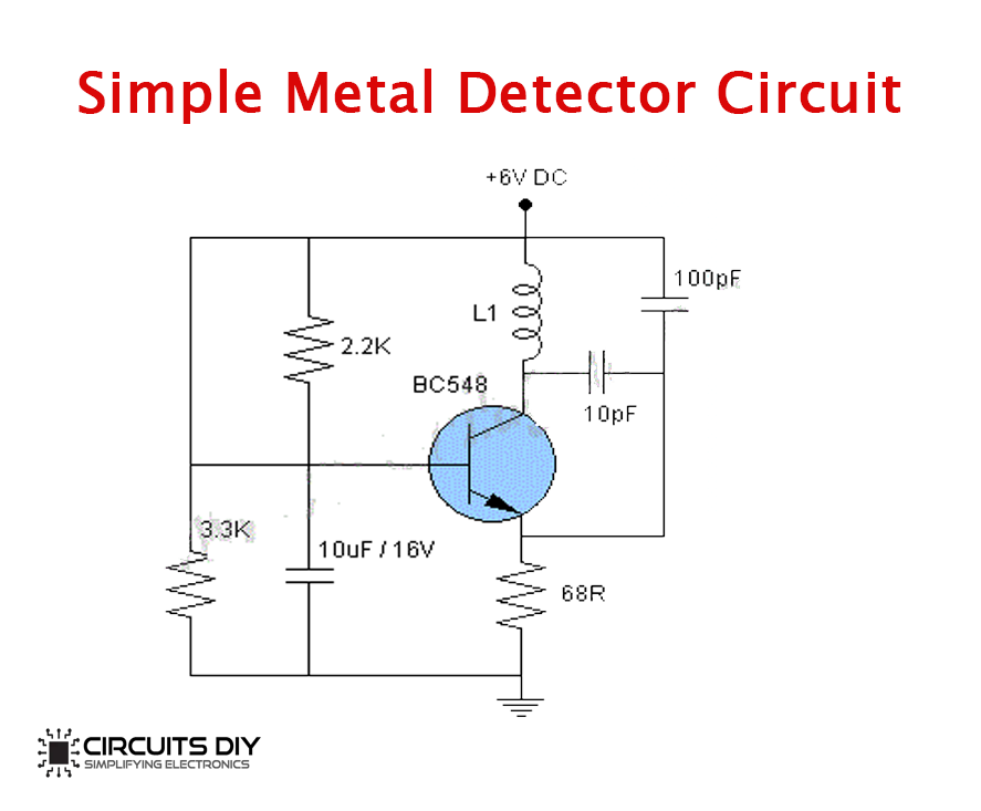
Metal detector circuits are simple electronic devices that find the presence of any metal within its range. These instruments function by sensing changes in the magnetic field caused by being in near distance to metallic objects. They serve for a number of purposes such as security screening, checking the accidental presence of undesirable metallic pieces in food products, etc.
Hardware Components
You will need the following parts to build this project.
| S.No | Component | Value | Qty |
|---|---|---|---|
| 1) | NPN Transistor | BC548 | 1 |
| 2) | PVC tubing | 1 cm | 1 |
| 3) | Enameled copper wires | – | As per need |
| 4) | Voltage regulator IC | LM7806 | 1 |
| 5) | Electrolytic Capacitor | 10uF/16V | 1 |
| 6) | Ceramic Capacitor | 100pF, 10pF | 2 |
| 7) | Resistors | 3.3KOhm, 2.2KOhm, 68Ohm | 3 |
| 8) | Battery | 9V | 1 |
| 9) | Battery Clips | – | 1 |
| 10) | Breadboard | – | 1 |
| 11) | Connecting Wires | – | As per need |
Circuit Diagram
Circuit Operation
This circuit is a low-cost metal detector using a single BC548 transistor and an old radio. When you place this metal detector circuit near any metal object you will hear a hissing sound from your AM radio, signaling the detection of a metallic object. L1 is equal to 60 turns of enameled copper wire wound on a 1cm PVC tube. The circuit power supply should be a 9V or 6V Battery.
6) LED Dimmer Circuit
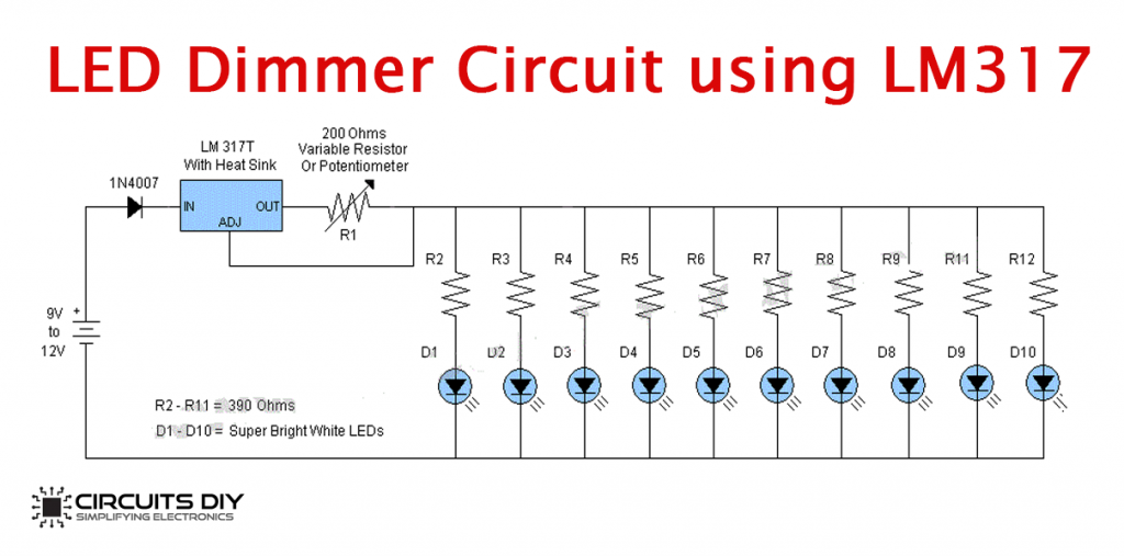
At No.6 in our list of Top 10 Simple Electronics project is the LED dimmer circuit. A simple circuit with the function of controlling the brightness of a light fixture. It does this by changing the voltage waveform being applied to the lamp or LED, thus making it possible to lower the intensity of the light output. they are used in devices such as mood lights, night lights & soft lights.
Hardware Components
You will need the following parts to build this project
| S.No | Component | Value | Qty |
|---|---|---|---|
| 1) | Voltage regulator IC | LM317 | 1 |
| 2) | Potentiometer | 200 Ohms | 1 |
| 3) | Diode | 1N4007 | 1 |
| 4) | LEDs | 5mm | 10 |
| 5) | Heat Sink (optional) | – | 1 |
| 6) | Resistors | 390Ω | 10 |
| 7) | Battery | 9V | 1 |
| 8) | Battery Clips | – | 1 |
| 9) | Breadboard | – | 1 |
| 10) | Connecting Wires | – | As per need |
Circuit Diagram
Circuit Operation
Here we are adjusting the brightness of 10 super-bright white LEDs, but the number of LEDs can be increased. The 200Ω Pot controls the current/brightness of LEDs. The total output current of LM317 is 1.5A, due to which we are using a separate current limiting resistor with each LED which protects them from the maximum current output of the IC.
7) Clap Switch Circuit
This circuit can be used to control AC loads such as lights, fans, etc through sound. With a proper sound-activated switch, dynamic control by sound becomes very useful, not just on robotic systems but also for home automation.
Hardware Components
You will need the following parts to build this project
| S.No | Component | Value | Qty |
|---|---|---|---|
| 1) | Comparator IC | LM393N | 1 |
| 2) | SPDT Relay | 9V/5V | 1 |
| 3) | Electret Microphone | – | 1 |
| 4) | NPN Transistor | 2N4401 | 1 |
| 5) | PNP Transistor | 2N4403 | 1 |
| 6) | Voltage regulator IC | LM7805 | 1 |
| 7) | Potentiometer | 20KΩ, 10KΩ | 2 |
| 8) | Diode | 1N4007 | 1 |
| 9) | Ceramic Capacitor | 120nF | 1 |
| 10) | Resistors | 100KΩ, 10KΩ | 3 |
| 11) | Battery | 9V | 1 |
| 12) | Battery Clips | – | 1 |
| 13) | Breadboard | – | 1 |
| 14) | Connecting Wires | – | As per need |
Circuit Diagram

Circuit Operation
Here, the audio input is taken from the electret microphone. Here a 120nF capacitor blocks the DC component of the audio, allowing only AC to flow to the transistor (2N4401). Now, this signal acts as a control signal to the base of the 2N4401 transistor
The 2N4401 transistor amplifies the sound signal received by the electret microphone. The amplified signal is then fed to the LM393N voltage comparator IC and a further amplified signal is received at the output pin 8 of the IC. A 2N4403 PNP transistor is used at the output of the IC to drive an SPDT relay switch.
8) LED Chaser Circuit
At No.8 in our list of Top 10 Simple Electronics project comes the famous LED Chaser circuit. An LED chaser circuit is a repeating sequencer usually made by combining a simple clock circuit with a counter circuit. It is widely used in places such as advertising displays and in running-light ‘rope’ displays in small discos, etc.
Hardware Components
You will need the following parts to build this project.
| S.No | Component | Value | Qty |
|---|---|---|---|
| 1) | Decade Counter IC | CD4017 | 1 |
| 2) | LEDs | 5mm | 10 |
| 3) | Pushbutton | – | 1 |
| 4) | Resistor | 1KΩ | 1 |
| 5) | Battery | 9V | 1 |
| 6) | Battery Clips | – | 1 |
| 7) | Breadboard | – | 1 |
| 8) | Connecting Wires | – | As per need |
Circuit Diagram

Circuit Operation
A pushbutton is connected to the clock input of the CD4017 decade counter IC. CD4017 has 10 output pins and each pin is connected to an LED. By default, the first output pin is on or high and the rest are off. Each time the clock input pin of 4017 IC detects a rise in voltage (from low to high), it turns off the current output and turns on the next sequential output. This swapping of outputs makes it look like the LEDs are chasing each other, the cycle continues until the last LED and then the output resets back to the first LED.
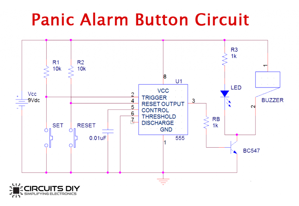
9) Simple Panic Alarm
A panic alarm is a simple electronic circuit that allows a person under stress to quickly call for help in case of an emergency. They are an important security feature in sensitive workplaces such as bank vaults & military compounds & are commonly used in high-risk areas such as security stations, prisons & checkpoints.
Hardware Components
You will need the following parts to build this project.
| S.No | Component | Value | Qty |
|---|---|---|---|
| 1) | Timer IC | NE555 | 1 |
| 2) | NPN Transistor | BC547 | 1 |
| 3) | Buzzer | 6V – 12V | 1 |
| 4) | LED | 5mm | 1 |
| 5) | Pushbuttons | – | 2 |
| 6) | Resistors | 10KΩ, 1KΩ | 4 |
| 7) | Ceramic Capacitor | 0.01μF | 1 |
| 8) | Battery | 9V | 1 |
| 9) | Battery Clips | – | 1 |
| 10) | Breadboard | – | 1 |
| 11) | Connecting Wires | – | As per need |
Circuit Diagram
Circuit Operation
Resistors R1 & R2 pull up TRIG pin 2 & RESET pin 4. On pressing the SET pushbutton, the trigger pin 2 turns low. Therefore, making the output of the lower comparator inside the 555 timer IC to go high for an instant. This sets the flip-flop & the OUT pin goes high & remains in this state until an external reset signal is provided. The process of resetting the 555 timer IC is done by pressing the RESET button. This makes the RESET pin to go low (less than Vcc/3) for an instant which is connected directly to a flip-flop through a transistor. The output signal reaches the base terminal of Q1 (BC547) & the transistor turns ON. Also turning ON the Buzzer & the LED connected to the transistor.
10) DC Variable Power Supply
Last on our list of Top 10 Simple Electronics Projects is the DC variable power supply. A DC adjustable power supply serves as an interface between a wall outlet and common power electronic equipment. A Variable power supply can be used for the testing & troubleshooting of small electronic projects making it a very versatile and useful project. This makes it a suitable candidate on the list of Top 10 Simple Electronics Projects.
Hardware Components
You will need the following parts to build this project.
| S.No | Component | Value | Qty |
|---|---|---|---|
| 1) | Step-down Transformer | 230V/28V, 3A, 50Hz | 1 |
| 2) | Voltage regulator IC | LM317T | 1 |
| 3) | Bridge rectifier | 3A/50V | 1 |
| 4) | Diode | 1N4002 | 2 |
| 5) | Heat Sink | – | 1 |
| 6) | Resistors | 100Ω | 1 |
| 7) | Potentiometer | 5.1KΩ | 1 |
| 8) | Electrolytic Capacitors | 2200μF/50V, 0.33μF, 100μF/50V, 10μF/50V | 4 |
| 9) | Breadboard | – | 1 |
| 10) | Connecting Wires | – | As per need |
Circuit Diagram

Circuit Operation
A 230V AC signal is applied at the primary of a non-CT transformer which steps it down to 28V 3A through mutual induction of the primary & secondary windings while maintaining the frequency at 50Hz. After which the 28V AC signal goes through a bridge rectifier that converts the AC signal into a rippling DC signal.
The rectified voltage is then fed into the input of an adjustable voltage regulator LM317. The diodes D1 & D2 are used to protect the regulator from excess flowing through it. The output voltage range is controlled by connecting a 5.1KΩ pot at the ADJ pin of the regulator.
So, above is our list of the top 10 Simple Electronics Projects for beginners to electronics. For more exciting projects relating to Arduino, Raspberry pi & NodeMcu Click here.