Introduction
Sounds play an influential role in the lives of humans. We attach sentiments and emotions to various sounds. For example, suppose you’re someplace and hear a fire alarm, it places you in a circumstance to leave that spot. Assuming you hear an emergency vehicle, you appeal to God for the wellbeing of an individual, in case you hear the police alarm, you get the information that something cruel occurs in your space. Do you want to know how these sirens are made? Let’s discuss that in this article. So, In this tutorial, we are going to make a “Three Siren Sound Generator Circuit Using UM3561”
Overview of UM3561 IC
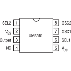
Pinout
- SEL 1: Pin 1: Selection Pin
- Vss: Pin 2: For negative supply/ground
- output: Pin 3: to generate a mono-tone sound signal.
- NC: Pin 4: Left unconnected
- Vdd: Pin 5: for positive supply
- SEL 2: Pin 6: Selection pin 2
- OSC1: Pin 7: Oscillator Pin, to set the frequency
- OSC2: Pin 8: Oscillator pin to set the frequency
Features
- Four sounds can be selected
- Power on reset
- Typical 3V operating voltage
- A magnetic speaker can be driven by connecting
- 8-pin DIP package from an NPN transistor
- Low-cost
- Low-power CMOS LSI is designed for use in alarm and toy applications.
Hardware Required
| S.no | Component | Value | Qty |
|---|---|---|---|
| 1. | IC | UM3561 | 1 |
| 2. | NPN Transistor | BC547 | 1 |
| 3. | Speaker | 8Ω | 1 |
| 4. | Potentiometer | 100KΩ | 1 |
| 5. | Zener diode | 3.3V | 1 |
| 6. | Push Button Switch | – | 3 |
| 7. | Breadboard | – | 1 |
| 8. | Resistor | 560Ω, 100KΩ, 10KΩ | 1, 1, 1 |
| 9. | Connecting wires | – | – |
| 10. | Battery | 9V | 1 |
| 11. | 2-Pin Connector | – | 2 |
Circuit Diagram
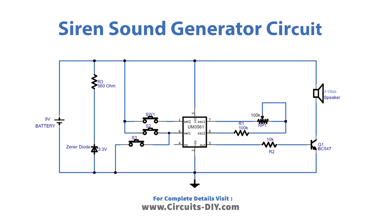
Working Explanation
In this Three Siren Sound Generator Circuit, we are using IC UM3561 having 8 pins. The supply provides a bias to the complete circuit. A Zener diode is also there to regulate the battery voltage. Pin 1 and 6 of an IC are select line pins that are connected with push-button. We wired oscillator pin 7 with a variable resistor. The variable resistor is there to maintain the oscillation. We connect the output pin to the 8Ω speaker through the NPN transistor.
When you press Switch 1 (S1) a sound will generate when you press Switch 2 (S2) the other sound will generate, and when you press pin 3 another speaker makes another sound at the output. Hence, the circuit can make three unique sounds.
Application and Uses
- We can use this in circuits to generate ambulance sirens.
- It can also be used to make a machine gun siren.
- Also, to generate fire bridges and other sirens.
- This circuit has great use in children’s toys